2
Role/ Features / Installation
Step 4
Connect the wires and cables to the lobby station.
Attach the lobby station to the flush mount box.
Secure the lobby station to the flush mount
box with 4 screws using the hex wrench.
Step 6
(1) Cable release button for DC power
supply cable
(2) DC cable from power supply unit
(3) Hooks for securing the DC cable
(4) Coaxial cable from external camera
(5) Wires from control box
(6) Wires from access controller
(7) Wires from electric lock
(8) Wire release button
(9) Connection terminal
(1)
(2) (3) (4) (5) (6) (7)
(8)
(9)
Image range
Approx.
115°
1,500 mm
700 mm
1,600 mm
2,300 mm
500 mm
Centre of
the camera
lens
Side view
Step 5
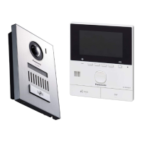
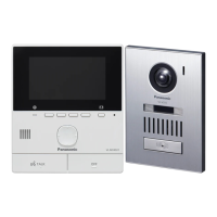
2-2. Lobby Station : VL-V900 (Installing the Lobby Station)
Approx.
170°
Approx.
500 mm
Top view
7
11
Hex wench
Water drain holes
 Loading...
