43
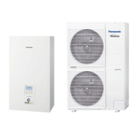
11.3.3.6 Drain Elbow and Hose Installation (Cooling model only)
Fix the drain elbow and packing to the bottom
of indoor unit, as shown in below illustration.
Use inner diameter 17 mm drain hose in the
market.
This hose must to be installed in a continuously
downward direction and in a frost-free
environment.
Guides this hose’s outlet to outdoor only.
Do not insert this hose into sewage or drain pipe
that may generate ammonia gas, sulfuric gas, etc.
If necessary, use hose clamp to further tighten the
hose at drain hose connector to prevent leakage.
Water will drip from this hose, therefore the outlet
of this hose must be installed in an area where the
outlet cannot become blocked.
Water Connecto
Packing
9
Drain Elbow
10
11.3.4 Connect the Cable to the Indoor Unit
1 Connecting cable between indoor unit and outdoor unit shall be approved polychloroprene sheathed 6 × 1.5
mm
2
flexible cord, type designation 60245 IEC 57 or heavier cord.
o Ensure the colour of wires of outdoor unit and the terminal no. are the same to the indoor unit’s
respectively.
o Earth wire shall be longer than the other wires as shown in the figure for the electrical safety in case of
the slipping out of the cord from the Holder (Clamper).
2 An isolating device must be connected to the power supply cable.
o Isolating device (Disconnecting means) should have minimum 3.0 mm contact gap.
o Connect the approved polychloroprene sheathed as below, type designation 60245 IEC 57 or heavier
cord to the terminal board, and to the other end of the cord to isolating device (Disconnecting means).
Power supply 1 cord (5 × 1.5 mm
2
)
Power supply 2 cord (3 × 1.5 mm
2
) (Only applicable for WH-S**09*3E8)
or
Power supply 2 cord (5 × 1.5 mm
2
) (Only applicable for WH-S**09/12/14/16*9E8)
3 To avoid the cable and cord being damaged by sharp edges, the cable and cord must be passed through a
bushing (located at the bottom of indoor unit) before being connected to the terminal block. The bushing must
be used and must not be removed.
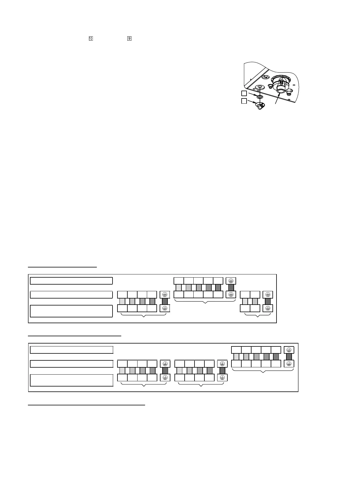
For model WH-S**09*3E8
Indoor unit/
Outdoor unit connection
1
1
2
2
3
3
4
4
5
5
L
L
N
N
Power Supply 2
Booster Heater
Power Supply
L
A1
L
A2
L
A3
N
L
A1
L
A2
L
A3 N
Power Supply 1
Main Power Supply or Main +
Backup Heater Power Supply
Terminal on the outdoor unit
Colour of wires (Connecting cables)
Terminal on the indoor unit
(Power Supply Cord)
Terminals on the isolating device from
power supply (Disconnecting means)
For model WH-S**09/12/14/16*9E8
Indoor unit/
Outdoor unit connection
1
1
2
2
3
3
4
4
5
5
L
B1
L
B2
L
B3
N
L
B1
L
B2
L
B3
N
Power Supply 2
Booster + Backup
Heater Power Supply
L
A1
L
A2
L
A3
N
L
A1
L
A2
L
A3
N
Power Supply 1
Main Power Supply
Terminal on the outdoor unit
Colour of wires (Connecting cables)
Terminal on the indoor unit
(Power Supply Cord)
Terminals on the isolating device from
power supply (Disconnecting means)
Connecting with external device (optional)
1 All connections shall follow to the local national wiring standard.
2 It is strongly recommended to use manufacturer-recommended parts and accessories for installation.
3 Maximum output power of booster heater should be ≤ 3 kW. Booster Heater cord must be (3 × min 1.5 mm
2
),
of type designation 60245 IEC 57 or heavier.
4 Two-way Valve shall be spring and electronic type, refer to “Field Supply Accessories” table for details. Valve
cable shall be (3 × min 0.5 mm
2
), of type designation 60245 IEC 57 or heavier, or similarly double insulation
sheathed cable.
 Loading...