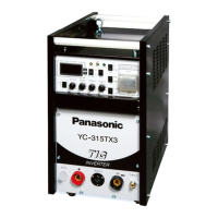
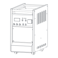
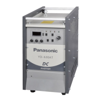
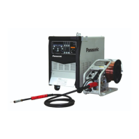
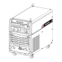
This document provides operating instructions for the Panasonic YC-315TX IGBT controlled DC TIG Arc Welding Power source.
Function Description:
The YC-315TX is a DC TIG welding machine that utilizes inverter technology controlled by IGBTs. It employs PWM (Pulse Width Modulation) controlled technology to deliver a constant welding current and stable welding arc. The machine is designed with multiple guard functions to ensure safety and prevent damage, such as stopping welding and alarming in cases of power abnormality, over-duty usage, or IGBT damage caused by over-current conditions. It also features an electric-shock-prevent switch on the printed circuit board, which can be activated when welding in environments with a risk of electric shock, to protect the operator. The device supports both TIG welding and DC stick welding operations. For TIG welding, it offers crater control (ON, OFF, REPEAT modes), pulse TIG welding with adjustable pulse current, frequency (low: 0.5-30 Hz, middle: 10-500 Hz), and pulse width. It also includes adjustable upslope and downslope timers for current conversion, a gas post-flow timer, and a spot-time adjustor for spot TIG welding. For stick welding, an arc drive current adjustor is provided. The machine's cooling type (water cooling or air) can be selected based on the torch in use. A flow switch is incorporated to protect water-cooled torches from burning by activating a warning lamp and stopping operation if the water flow rate is too low.
Important Technical Specifications:
- Model No.: YC-315TX3HJF
- Rated Input Voltage: 415 V
- Allowable Fluctuation: 415 ± 10%
- No. of Phase: 3
- Rated Frequency: 50/60 Hz
- Rated Input (TIG): 10.37 KVA / 9.17 KW
- Rated Input (STICK): 14.33 KVA / 12.5 KW
- Rated No-Load Voltage: 61 V
- Output Current: 4-315 A
- Initial Current: 4-315 A
- Pulse Current: 4-315 A
- Crater Current: 4-315 A
- Rated Output Voltage (TIG): 10.2-22.6 V
- Rated Output Voltage (STICK): 20.8-32.6 V
- Rated Duty Cycle: 60%
- Pre-flow: 0.3 s
- Post-flow: 2-20 s
- Up Slope Timer: 0.1-5 s
- Down Slope Timer: 0.2-10 s
- Pulse Frequency (Middle): 10-500 Hz
- Pulse Frequency (Low): 0.5-30 Hz
- Pulse Width: 5-95%
- Crater Control Process: Three modes (ON, OFF, REPEAT)
- Outside Dimension: 327 × 620 × 620 mm
- Weight: 43 kg
- Degree of Protection: IP21S (requires appropriate coverage in case of rain)
- Environmental Conditions: Indoor, dry, dust-free, out of direct sunlight, ambient temperature -10 to 40 °C, at least 20 cm clearance from nearest wall, free of unusual vibration or shock, no generation of oil vapor or harmful corrosive gas.
Usage Features:
The YC-315TX is widely applied in petrochemical, power plant, construction, and pipeline construction industries.
- Power Supply Connection: Requires a three-phase 415V power supply with a facility capacity of 30 KVA or more, and a 30A fuse/earth leakage breaker. Input cables should be 6 mm² or more, output cables 35 mm² or more, and general cables 14 mm² or more. For single-phase use, connect to "U" and "V" terminals, keeping output current below 180A.
- Grounding: Essential for electric shock protection and to prevent malfunctioning from high-frequency waves. The case of the welding power source and base metal must be properly grounded. Grounding conductors should be checked daily for disconnection or damage.
- TIG Welding:
- Set the welding process switch to "TIG welding".
- Turn on the switch box and the power switch on the front panel. The power lamp (green) will turn on, and the cooling fan will rotate.
- Check gas flow by setting the gas check switch to "Check"; the gas valve opens, and argon gas is supplied.
- Set the gas check switch to "Weld" to begin welding. Arc generation occurs by pressing the torch switch near the base metal.
- Welding current is controlled via crater control, torch, and pulsation switches.
- After welding, close the argon gas cylinder and stop cooling water if used.
- Stick Welding:
- Set the welding process switch to "STICK" and the torch select switch to "Air".
- Turn on the switch box and the power switch on the front panel. The power lamp (green) will turn on, and the cooling fan will rotate.
- Output voltage is generated between the output terminals.
- Perform stick welding as per normal procedure, adjusting welding current via the front panel adjustor.
- After welding, turn off the power switch and the switch box switch.
- Tungsten Electrode Selection: Refer to the provided table for appropriate electrode core diameter based on welding current (DC Electrode Negative). For example, a 1.6 mm electrode is suitable for 70-150 A, while a 3.2 mm electrode is for 250-315 A. YWTh (2% thorium tungsten) electrodes are recommended.
- Shielding Gas: Use welding argon gas for TIG welding. Impurities like oxygen, moisture, or nitrogen can reduce shielding effectiveness.
- Filler Wire: Selection depends on base metal type, thickness, and welding current. A reference table is provided for filler wire diameter based on welding current.
- Cooling Water: For water-cooled torches, a minimum supply of 1 liter/minute is required. The welder will not operate if the flow is below 0.7 liter/minute, and a "Water" warning lamp will illuminate. Antifreeze solution (glycol type, less than 20% ratio) can be used in cold conditions.
Maintenance Features:
Periodic maintenance and checking are crucial for safe operation. The primary switch box (or no-fuse breaker) must be turned off before checking internal or external terminals.
- Daily Check List:
- Check for unusual vibration, buzzing, or smell.
- Inspect cable connections for signs of unusual heat.
- Verify smooth rotation of the cooling fan when the power switch is on.
- Check for any malfunctioning switches.
- Confirm correct cable connection and insulation.
- Inspect cables for any damage.
- Checking Every 3-6 Months:
- Electric Connection: Check fixing screws on input and output cable connections for looseness or insufficient contact, and inspect for insulation problems.
- Grounding Conductor: Confirm the machine's case is fully grounded and that the conductor is not disconnected or broken.
- Inside of the Machine: Dust accumulation on heat sinks or transformer windings can lead to inefficient heat radiation, insulation degradation, and potential burnout of semiconductors and transistors. Clean the machine every 3-6 months by blowing compressed dry air after removing the top and side panels. Wait at least five minutes after turning off power to allow capacitors to discharge before touching internal parts.
- Adjustment of High Frequency: The spark electrode spacing is factory-adjusted to 0.8 mm. Polish the electrode if its surface is uneven or dirty, and readjust spacing to 0.8 ± 0.1 mm.
- Care Points for Insulation Pressure Test and Measurement of Insulation Resistance: Due to numerous transistors and semiconductor components, specific precautions must be followed during these tests:
- Disconnect and short-circuit the three input terminals from the distribution box.
- Disconnect and short-circuit the two output terminals from the secondary side current cable.
- Short-circuit the anode and cathode of the main circuit primary diode D1, the emitter and collector of the main transistor Q1-Q2, and the anode and cathode of the secondary diode D2-D3 and thyristor.
- Remove case grounding (totaling 6 locations).
- Flow Switch Maintenance: If the flow switch is used for a long time, its axis and float may accumulate fur or rust, causing malfunction. Periodically clean the flow switch by removing the right side panel, water inlet fixture nut, and cap, then cleaning the fur and rust from the flow switch, axis, and float.
- Filter Precautions: To prevent dust or fur accumulation in the water flow switch and torch water conduct, install the provided filter to the water inlet on the rear side of the welding machine. Clean the filter once or twice per month by removing the adapter, taking out the filter, and washing or brushing the wire net.
- Troubleshooting: A guide is provided for common abnormalities (e.g., power switch tripping, warning lamps, arc issues, gas flow problems) and their corresponding checking points. If issues persist or are not covered, contact the manufacturer's agent.