This document provides operating instructions for the Panasonic MIG/MAG Welding Gun, Model No. YT-40MFW. It covers safety precautions, usage, technical specifications, and maintenance.
Function Description
The Panasonic YT-40MFW is a MIG/MAG welding gun designed for use with Panasonic welding power sources. It facilitates the feeding of welding wire and the delivery of shielding gas and welding current to the weld pool. The gun is capable of both MIG (Metal Inert Gas) and MAG (Metal Active Gas) welding processes, including CO2 welding. It supports welding with aluminum, stainless steel, and carbon steel wires. The gun features integrated current and voltage adjustment buttons for convenient control during operation.
Important Technical Specifications
Product Model: YT-40MFW
Product Serial Number: YT-40MFW2HTF
Welding Current:
Rated Load Duration:
- MIG:
- MAG:
- CO2 Welding: 400A-100%
Applicable Welding Wire: Aluminum, stainless steel (carbon steel)
Applicable Welding Wire Diameter: Ø1.0mm, Ø1.2mm, Ø1.4mm, Ø1.6mm
Applicable Gas: CO2, 20%CO2+80%Ar, Ar
Cable Length: 3m
Weight: 2.65kg
Barrel Shape:
Executive Standard: EN IEC 60974-7:2019
Rated Voltage: DC 113V
Torch Switch Voltage: DC 24V
Orientation: Manual
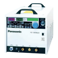
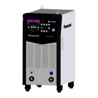
Adaptive Welding Power Source: YD-500GP5HNX
Adaptive Wire Feeder: YW-50DNW1HAG
Cooling Method: Water cooling
Gas Pressure (Inlet):
- Minimum: 0.10MPa
- Maximum: 0.35MPa
Coolant Flow: >1L/min
Coolant Pressure:
- Maximum: 0.35MPa
- Minimum: 0.20MPa
Minimum Cooling Power Required for Welding Gun: 1.0kW (for 3m cable length; increases with longer cable)
Usage Features
Safety Precautions:
- General: Always use the welding power source only for welding. Comply with all instructions, safety warnings, cautions, and notes. Ensure proper grounding of the welding power source and base metal. Turn off power and wait at least five minutes for capacitors to discharge before maintenance. Do not use undersized, worn, damaged, or bare wired cables. Connect cables firmly and insulate connections. Keep all covers and panels securely in place. Do not handle with torn or wet gloves. Wear safety harness when working above floor level. Turn off all equipment when not in use. Perform periodic checks and repair/replace damaged parts.
- Ventilation and Protective Equipment: Welding generates fumes and gases that can be hazardous. Use local exhausters or wear protective breathing gear, especially in confined areas or when welding coated steel plates. Avoid welding near degreasing, cleaning, or spraying operations as this can generate toxic gases.
- Fire, Explosion, Blowout: Remove combustible materials from the work site or cover them with fireproofing. Do not weld near combustible gases. Avoid bringing hot base metal near combustibles immediately after welding. Remove flammables from hidden places when welding ceilings, floors, or walls. Properly connect and insulate cables to prevent fire. Connect the base metal cable closest to the welding part. Do not weld sealed tanks or pipes containing gas. Keep a fire extinguisher nearby.
- Electric Shock: Do not touch live parts.
- Arc Flash/Spatter/Noise: Install a protective curtain. Wear safety glasses with light-blocking structures or a protective mask. Wear protective clothing (leather gloves, leg cover, leather apron, long-sleeve shirts). Wear noise-proof equipment if noise levels are high, especially with larger welding currents or AC TIG/MIXTIG welding.
- Gas Cylinder and Regulator: Handle gas cylinders properly according to laws and in-house standards. Use the recommended gas flow regulator and read its manual. Secure the cylinder to a dedicated stand. Do not expose to high temperatures. Do not bring your face close to the discharge outlet when opening the valve. Install a protective cap when not in use. Do not hang the torch on the cylinder or touch it with the electrode. Do not disassemble or repair the regulator.
- Rotating Parts: Keep away from rotating parts like cooling fans and wire feeder rollers to prevent injury. Keep all covers closed during operation. Maintenance should only be performed by educated and skilled persons, with proper fencing to prevent unauthorized access.
- Welding Wire: Do not perform inching operations or pull the torch switch with your eyes, face, or body close to the torch end, as the wire can extend and cause injury. When using a resin liner, straighten the torch cable and reduce the preset feed amount before wire inching. Replace damaged liners or cables to prevent gas leaks or dielectric degradation.
- Insulation Deterioration: Maintain sufficient distance from the welding power source during welding/grinding to prevent spatters or iron particles from entering. Periodically check and maintain to prevent insulation deterioration due to dust/dirt. If spatters or iron particles enter, turn off power and blow them out. Replace damaged liners/cables. Do not leave panels or bolts open.
Environmental Conditions:
- Operating Temperature: -10℃ to +40℃
- Transport/Storage Temperature: -25℃ to +55℃
- Humidity: Not exceeding 90% at 20℃
- Do not use the torch in rain, snow, or similar weather conditions.
Cooling Water (for water-cooled torch):
- Ensure cooling-water flow of more than 0.7L/min.
- Water pressure at the torch entrance: 0.1-0.3MPa for 4m cable, 0.15-0.3MPa for 8m cable. Insufficient flow can cause torch burnout.
- Never use a water-cooled torch for air cooling.
- Never use a water-leaked torch to prevent electrical shocks.
Cable Hose:
- Do not place the hose cable on hot base metal immediately after welding.
- Avoid loading heavy material on the cable hose or bending it by force, as this can cause torch burnout.
- If the hose is bent excessively, it can cause poor wire feeding and snaking. Use it as straight as possible, with a bending radius not less than 800mm (for the main cable) and 400mm (for the torch end).
Welding Operation and Exchange of Parts:
- Do not touch hot parts (nozzle, electrode, torch body).
- Wear protective gear (leather gloves) during welding.
- Exchange torch parts only after turning off the power supply and when the temperature is lower.
- Always use "Panasonic" marked genuine parts for safety and good welding.
- Wear protective glasses when grinding electrodes and follow safety standards for grinding machines.
Preparation for Using:
- Straighten the welding gun before operating, especially for slow wire feeding.
- Maintain a distance of 10-30mm between the nozzle and base metal, corresponding to the welding current.
- Confirm the relationship between welding current and load duration, ensuring operation within the rated range.
- Install a shunt to prevent poor sealing and insulation.
- Ensure the hose is as straight as possible to prevent poor wire feeding and snaking.
Connection Method:
- Welding Gun Cable: Install a long wire feed tube. Connect the lock nut on the welding torch to the wire feeder's connection part and tighten securely. Before connecting, blow off spatter and wire powder. Ensure the pin is correctly inserted into the European connector.
- Welding Torch Water Pipe: Connect the water supply pipe to the cooling water circulation device's supply pipe, and the drain pipe to its return pipe. The quick-plug structure should click into place. Pull back to confirm connection. Incorrect connection can cause water leakage, scalds, torch burns, fire, and electric shock. Use antifreeze as coolant in icing environments. Blow out coolant with compressed air when not in use for a long time.
Parts Installation Method:
- Wire Feeding Tube (Resin for Aluminum): Straighten the cable. Insert the long wire feed tube into the guide wire tube, remove the contact tip, and confirm full insertion. Install the contact tip, adjust the clamp, and hand-tighten the lock nut. Connect the torch to the wire feeding device and tighten the torch lock nut. The wire feeding tube should be cut to L=8mm from the inner end surface of the European connector female seat.
- Wire Feeding Tube (for Carbon Steel): Straighten the cable. Insert the wire feeding tube into the guide wire tube. When replacing, cut the front end of the tube to ensure the extension part L is 4-7mm. Hand-tighten the lock nut. Exercise caution when inserting the steel wire feed tube, keeping head, face, and other body parts away to prevent injury from rebound.
- Tip Installation: Unscrew the nozzle, then use a wrench to unscrew the old conductive tip. Install and tighten the new contact tip with a wrench. Turn off the welding power switch before replacing tips, nozzles, or other parts.
Current and Voltage Adjustment Buttons:
- Current: Each press of the "+" or "-" button adjusts current by 2A. Press and hold for continuous adjustment.
- Voltage: Each press of the "+" or "-" button adjusts voltage by 0.2V. Press and hold for continuous adjustment.
Maintenance Features
- Periodic Checks: Perform periodic checks without fail and repair or replace any damaged parts before using the power source.
- Insulation Maintenance: Perform periodic check and maintenance work to prevent insulation deterioration due to accumulated dust or dirt. If spatters or iron particles get into the welding power source, turn off the power switches and blow them out.
- Cable and Liner Replacement: Replace any damaged liner or cable with a new one, as damage can cause gas leak or dielectric degradation.
- Cleaning: Before connecting the welding gun cable, use an air gun or other tools to blow off spatter and welding wire powder from connection surfaces. If the conductive surface is scratched or knocked, replace it with a new "connector body" to prevent fire due to heating.
- Genuine Parts: When replacing parts, always use genuine Panasonic parts to ensure optimal performance.
- Coolant Management: In environments where icing is possible, use antifreeze as the coolant. When the welding torch is not used for a long time, use compressed air to blow the coolant out from the water supply port to prevent damage.
- Professional Maintenance: Maintenance and repair work should only be performed by educated and skilled persons who thoroughly understand welding machines. During such work, provide fencing around the machine to prevent unauthorized access.
- Disposal: In case of disposal, sign an assignment agreement with an authorized organization for proper disposal treatment.