Step I
A.
Co
Do
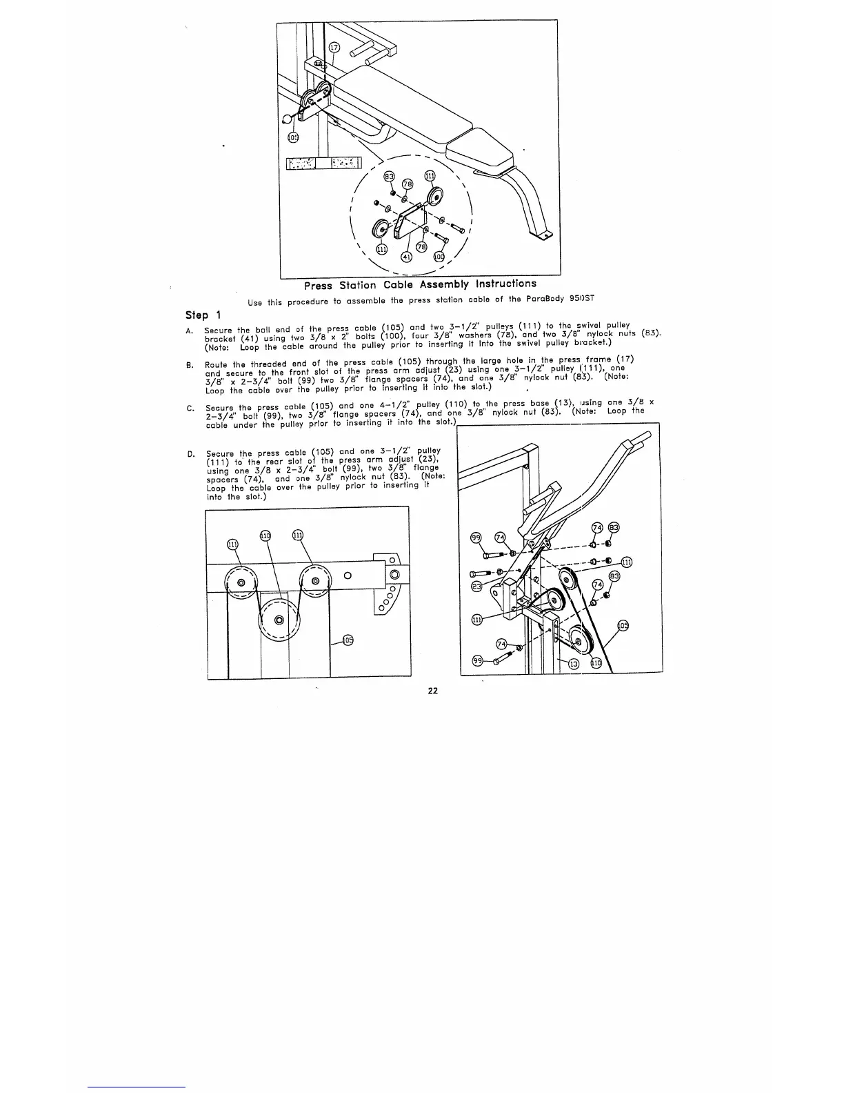
Press Station Cable Assembly Instructions
Use this procedure to assemble the press station cable of the ParaBody gSI)ST
Secure ’~he ball end of the press cable (105) and two 3-1/2" pulleys (111) to ’~he swivel pulley
bracket (41) using two 3/8 x 2" bolts (100), four 3/8" washers (78), and two 3/8" nylock nuts
(Note: Loop the cable around the pulley prior to inserting it into the swivel pulley bracket.)
Route the ~hreaded end of the press cable (105) through the large hole in ~he press frame (17)
and. secure to.the front slot of th
2
press arm adjust (23) using one ~-1/2" pulley (’111),
3/8 x 2-3/4 bolt (99) two 3/8 flange spacers (74), and one 3/8 nylock nut (8~).
Loop the cable over the pulley prior fo inserting if inio the slot.)
Secure the press cable (19,~) and one 4’1/2" pulley (110) to,,~he press base (15), usfng one
2-3/4" bolt (99), two 3/8 flange spacers (74), and one 3/8 nylock nut (83). (Note: Loop
cable under the pulley prior to inserting it into the slot.)~
Secure the press cable (10-5) and one 3-1/2" pulley
(111) to the rear slot o!, the press arm adjust (23),
using one 3/8 x 2-3/4 b.o, lt (99), two 3/8" flange
spacers (74), and one 3/8’ nylock nut (83). (Note:
Loop the cable over the pulley prior fo inserffing Tf
into the slot.)
22