Page 94 · Robotics with the Boe-Bot
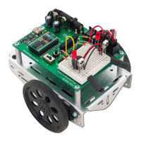
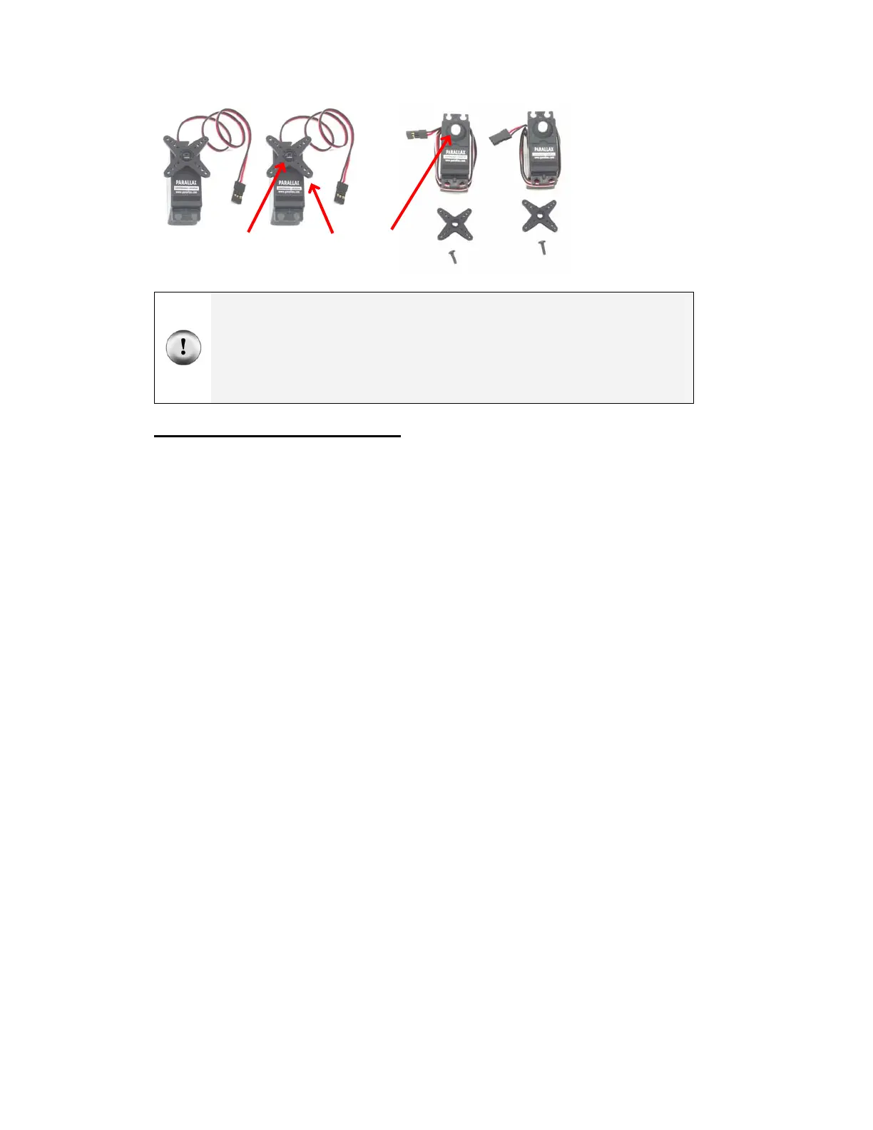
Figure 3-3
Servo Control
Horn Removal
Parts (left);
after following
instructions
(right).
Stop!
√ Before this next step, you must have completed these activities from Chapter 2: Your
Boe-Bot’s Servo Motors
• Activity #3: Connecting the Servo Motors
• Activity #4: Centering the Servos
Mounting the Servos on the Chassis
Parts List:
See Figure 3-4.
(1) Boe-Bot chassis (partially
assembled)
(2) Parallax Continuous Rotation
servos
(8) Pan Head Screws, 3/8″ 4-40
(8) Nuts, 4-40
Instructions:
√ Attach the servos to the chassis using the
Phillips screws and nuts. Note that for best
performance, you must place the face of
each servo through the rectangular window
from inside the chassis rather than dropping
them in from the outside.
√ Use pieces of masking tape to label the
servos left (L) and right (R).
Control
horn
Phillips
screw
Output
shaft
 Loading...