Page 108 · Robotics with the Boe-Bot
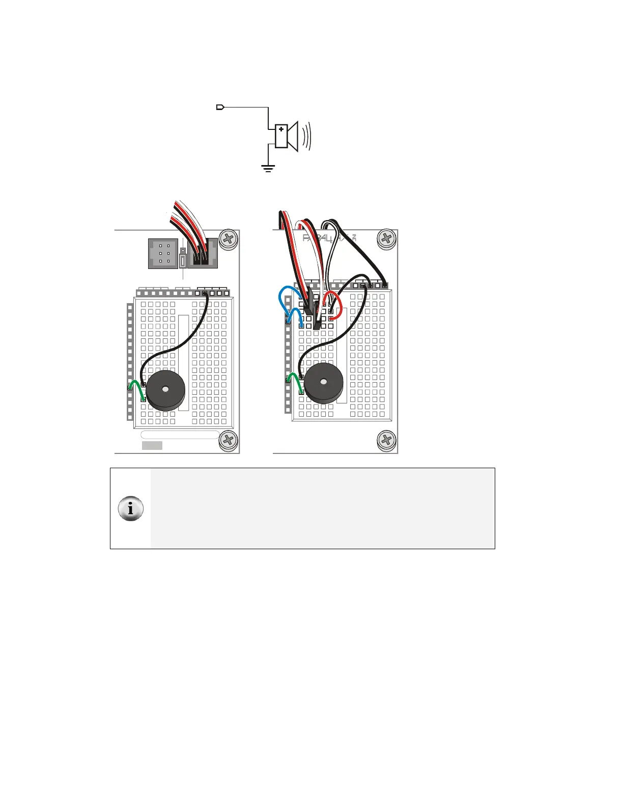
√ Build the circuit shown in Figure 3-17 and Figure 3-18.
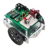
P4
Vss
Figure 3-17
Program Start/Reset
Indicator Circuit
P15
P14
P13
P12
P11
P10
P9
P8
P7
P6
P5
P3
P2
P1
P0
P4
X2
X3
Vdd VssVin
Board of Education
© 2000-2003
Rev C
Vdd
Black
Red
X4 X5
15 14 13 12
To Ser v os
+
P15
P14
P11
P13
P12
P4
P10
P9
P8
P7
P6
P5
P3
P2
P1
P0
X2
X3
Vdd VssVin
Rev B
(916) 624-8333
www.parallax.com
www.stampsinclass.com
To S ervos
+
HomeWork Board
Figure 3-18
Wiring Diagrams for
the Program
Start/Reset Indicator
Circuit
Board of Education
(left) and HomeWork
Board (right).
The piezospeaker and servo circuits will remain connected to your board for the rest
of the activities in this text.
All circuit schematics from this point onward will show circuits that should be added
to the existing servo and piezospeaker circuits.
All wiring diagrams will show the circuit from the schematic that comes just before it
along with the servo and piezospeaker circuit connections.