Page 168 · Robotics with the Boe-Bot
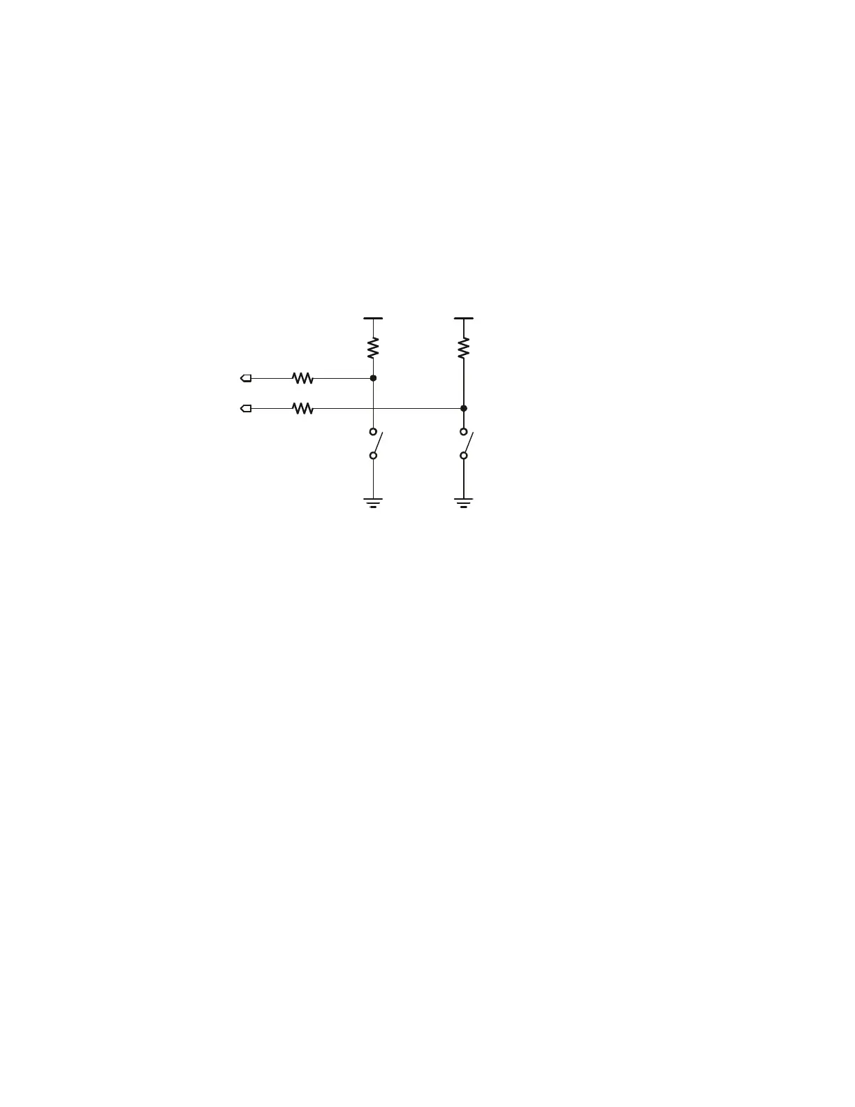
The next step is add the whiskers circuit shown in Figure 5-4 to the piezospeaker and
servo circuits you built and tested in Chapter 2 and Chapter 3.
√ If you have a Board of Education, build the whiskers circuit shown in Figure 5-4
using the wiring diagram in Figure 5-5 on page 169 as a reference.
√ If you have a HomeWork Board, build the whiskers circuit shown in Figure 5-4
using the wiring diagram in Figure 5-6 on page 170 as a reference.
√ Make sure to adjust each whisker so that it is close to, but not touching, the 3-pin
header on the breadboard. A distance of about
1
/
8
″ (3 mm) is a recommended
starting point.
P7
P5
Vss Vss
Vdd Vdd
Right
Whisker
Left
Whisker
10 k
Ω
10 k
Ω
220
Ω
220
Ω
Figure 5-4
Whiskers
Schematic