Chapter 5: Tactile Navigation with Whiskers · Page 171
Testing the Whiskers
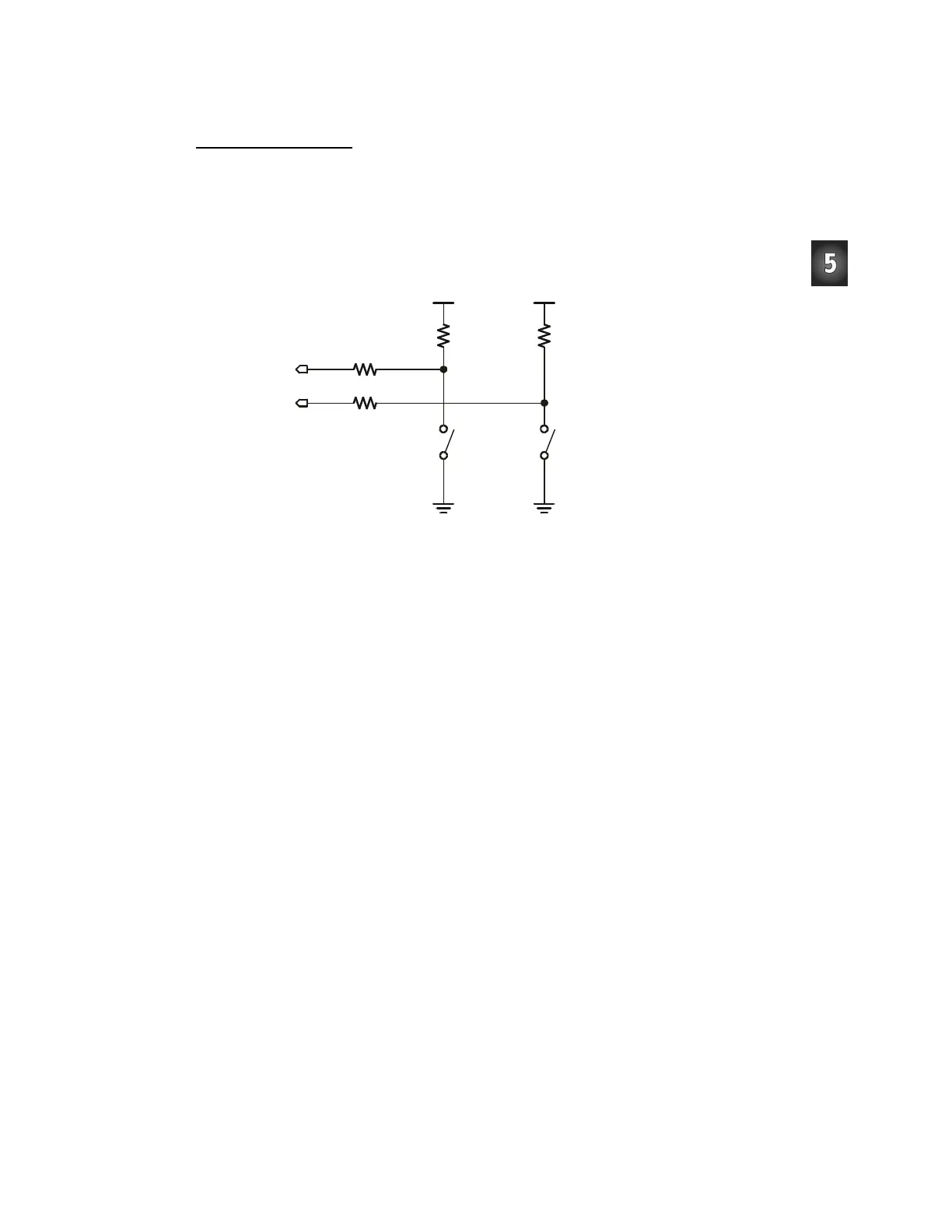
Take a second look at the whiskers schematic (Figure 5-7). Each whisker is both the
mechanical extension and the ground electrical connection of a normally open, single-
pole, single-throw switch. The reason the whiskers are connected to ground (Vss) is
because the plated holes at the outer edge of the board are all connected to Vss. This is
true for both the Board of Education and the BASIC Stamp HomeWork Board. The
metal standoffs and screw provide the electrical connection to each whisker.
P7
P5
Vss Vss
Vdd Vdd
Right
Whisker
Left
Whisker
10 k
Ω
10 k
Ω
220
Ω
220
Ω
Figure 5-7
Whiskers
Schematic –
A Second
Look
The BASIC Stamp can be programmed to detect when a whisker is pressed. I/O pins
connected to each switch circuit monitor the voltage at the 10 kΩ pull-up resistor.
Figure 5-8 illustrates how this works. When a given whisker is not pressed, the voltage at
the I/O pin connected to that whisker is 5 V. When a whisker is pressed, the I/O line is
shorted to ground (Vss), so the I/O line sees 0 V.
All I/O pins default to input every time a PBASIC program starts. This means that the
I/O pins connected to the whiskers will function as inputs automatically. As an input, an
I/O pin connected to a whisker circuit will cause its input register to store a 1 if the
voltage is 5 V (whisker not pressed) or a 0 if the voltage is 0 V (whisker pressed). The
Debug Terminal can be used to display these values.
 Loading...