DOC-0017-07-EN: AC20 Series - EtherCAT Option
10 (58) DOC-0017-07-EN-B 04.04.2023
6.2 Fitting the Option
Frames 2 – 5
The Communication Interface Option Cards are intended to be customer installed.
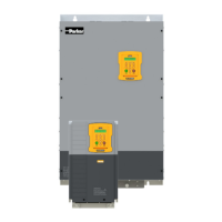
The control module housing cover will need to be removed prior to option card installation.
1. Use a T9 TORX driver to partially unscrew the two 3x12
countersunk fixings along the top of the product.
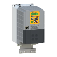
2. Insert a flat head screwdriver into the moulding features and
lever the control module housing away from the power
3. Unhook the bottom of the control module
housing from the power stack.
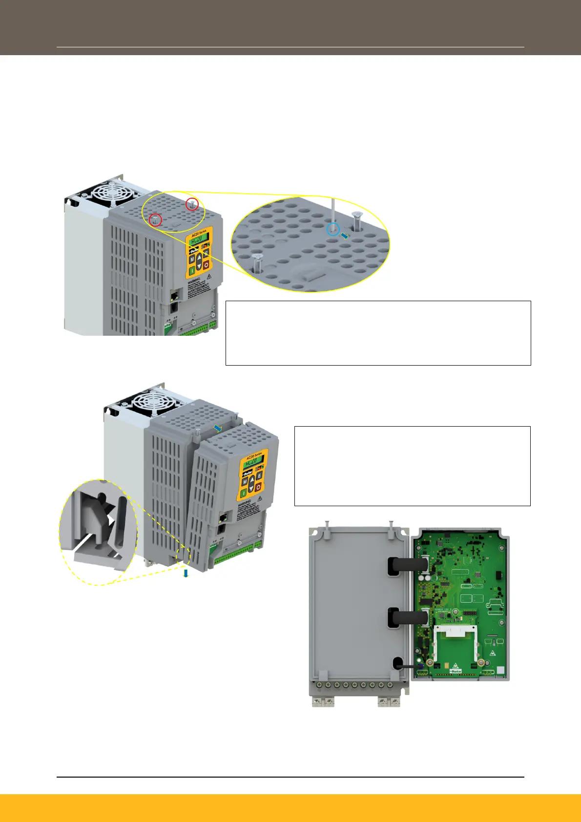
4. Gently turn the control module upside down
so it rests to the right of the power stack,
with the interface cables still connected.
 Loading...