DOC-0017-07-EN: AC20 Series - EtherCAT Option
12 (58) DOC-0017-07-EN-B 04.04.2023
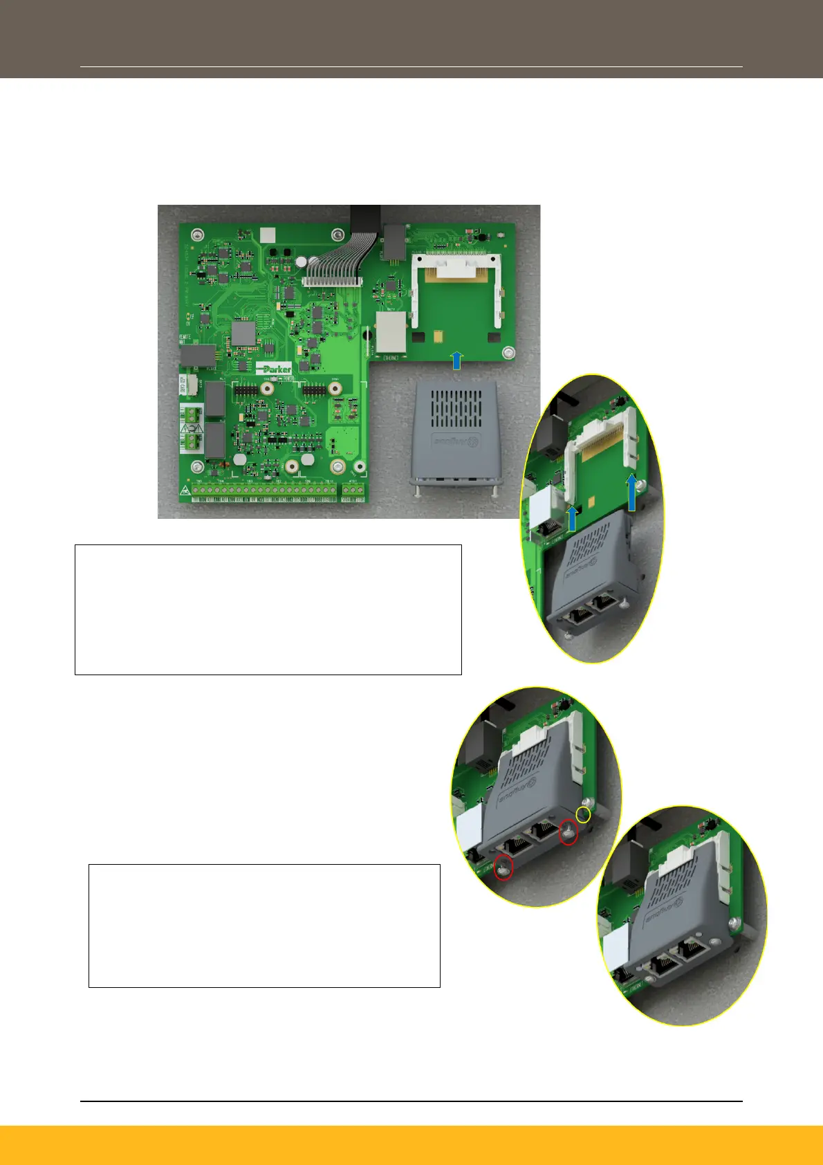
Frame 6 – 10
On Frames 6 – 10, the lower terminal cover will need to be removed prior to option card installation.
In the event that the Communication Interface Option Card needs to be removed, perform steps 2 & 3 in
reverse.
1. Remove the Comms Interface Option card from its
packaging.
2. Slide the Comms Card along the PCB using the
connector features for alignment.
Note: The front facia of the Option should be loose
at this point.
3. When the Comms Interface Option Card is fully
engaged in the connector and its housing has
hocked onto the edge of the PCB, fully tighten
the two T8 screws on the front facia.
4. Check that the Option Card is secure and that
it cannot slide out.
 Loading...