Important Notes:
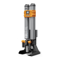
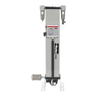
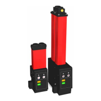
• e default inlet valve conguration for CDAS HL / OFAS HL / FBP HL is Normally Closed (N/C).
• In this conguration, when the remote switch is closed and the ½ cycle is completed, the inlet and exhaust valve will be closed.
ere will be no air ow through the dryer, protecting the desiccant bed.
• e optional inlet valve conguration for CDAS HL / OFAS HL / FBP HL is Normally Open (N/O).
• If the dryer is congured for Normally Open operation, this will allow compressed air to ow through the dryer whilst the
controller is powered o or not cycling from one column to another due to a remote stop being activated.
• Flowing compressed air through a non-cycling dryer will cause damage to the desiccant bed, invalidating warranty.
• Normally Open conguration is to be used at the user’s risk.
26
Medium Flow Compressed Air Dryers - IOMI.
INLET VALVE
CONFIGURATION
DEFAULT or OPTION POWER LOSS
REMOTE STOP
ACTIVATED
DESICCANT BED
PROTECTED
Normally Closed (N/C) Default
Inlet Valves Closed
No compressed air ow
through dryer
Inlet Valves Closed
No compressed air ow
through dryer
Yes
Normally Open (N/O) Option
Inlet Valves Open
Compressed air ow through
dryer
Inlet Valves Open
Compressed air ow through
dryer
No
Purge Economy Connection
Purge economy can only operate if the dryer is installed directly aer the compressor AND before an air receiver. Under no circumstances
should purge economy be connected if there is an upstream, wet air receiver as this will saturate the desiccant bed, lose dewpoint and
invalidate the dryer warranty.
Purge economy requires a wired connection to the air compressor and relies on the compressor being tted with a relay that will change state
as the compressor switches between “on load” and “o load”.
At the Compressor
• Identify the On Load / O Load Relay
• Determine which terminal connection on the relay is open when the compressor is on load and closes when the compressor is
o load
• is terminal and the common terminal of the relay will be used to form a digital switch.
• A 2-core cable will be required between the compressor relay and the dryer.
At the Dryer
• e dryer control board supplies the 24V DC required to
operate the Purge Economy Function.
• Connect one core of the cable from the “+” on the dryer
control board to the connection on the relay that is closed
when the compressor goes o load.
• Connect the other core of the wire between the common
connection on the relay and the P/E connection on the
control board.

 Loading...


