2: Calibrating the Control Board
2.1 CONNECT THE AUXILIARY SUPPLY: Remove 3-phase fuses (6). Re-instate branch circuit protection or circuit
breaker (8). Check that the auxiliary voltage is correct. The Keypad will now display the Welcome screen.
AUXILIARY POWER ONLY IS CONNECTED AT THIS STAGE
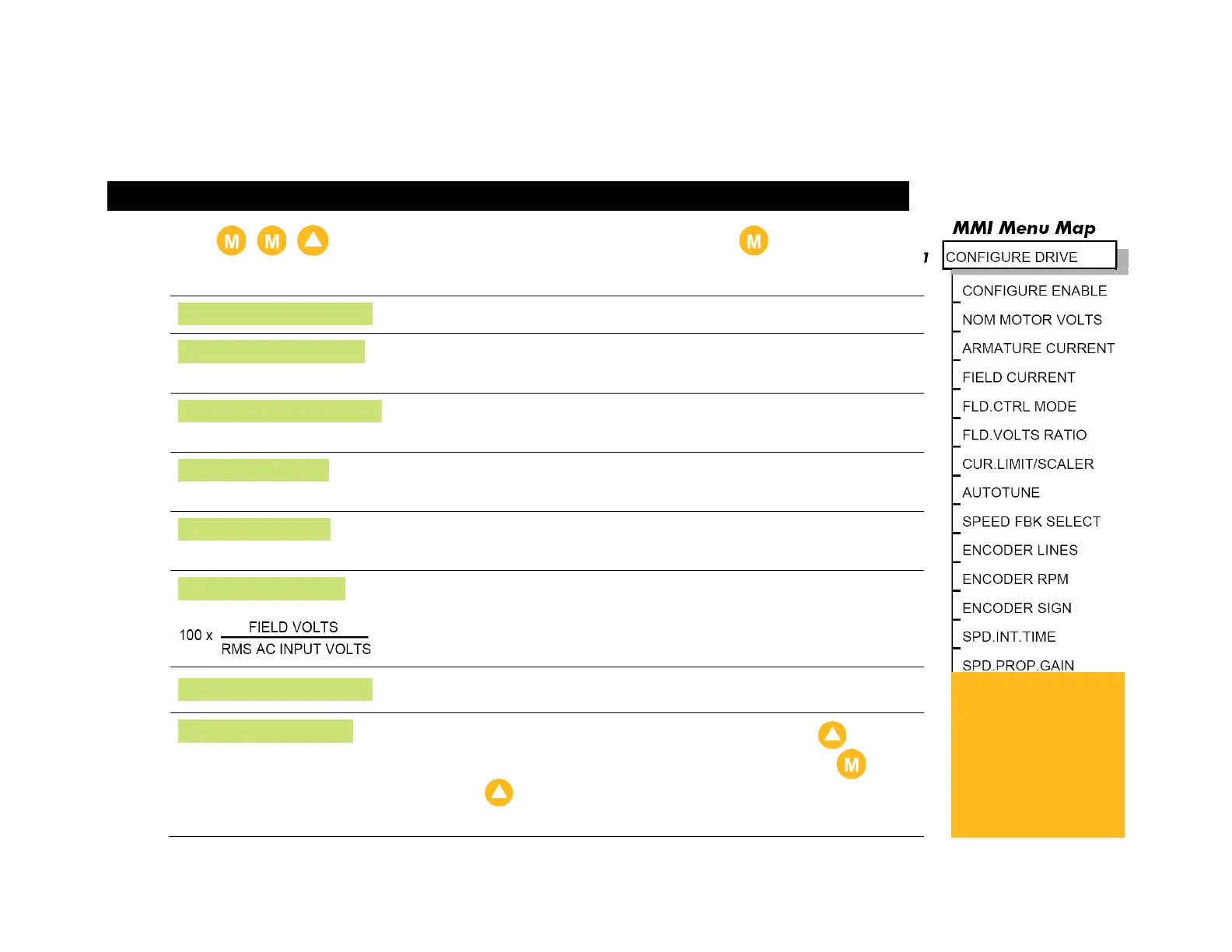
Press , , to display the CONFIGURE DRIVE menu. Press again to display
the first parameter. Set the following parameters in the menu:
Set to ENABLED. All LEDS on the Keypad will flash.
Enter Armature Voltage value (VACAL) from the motor rating
plate
Enter the armature current value (IA CAL) from the motor
rating plate.
Enter the nominal field current (IF CAL) from the motor rating
plate.
Check that the field control mode is set to VOLTAGE
CONTROL.
Enter the calculated ratio into the parameter given by the
equation. The default setting of 90% is the maximum value
obtainable, i.e. field output = 0.9 x Vac.
Set to DISABLED. The Keypad's LEDs will stop flashing.
Exit the CONFIGURE DRIVE menu and press the (UP)
key to display the PARAMETER SAVE menu. Press .
Press the (UP) key as instructed to save your settings.
Refer to 3.3.
Refer to the
Product Code on
the drive's Rating
Label to confirm
the drive's
specification.
 Loading...


