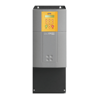
Do you have a question about the Parker DC590PR Series and is the answer not in the manual?
Details requirements for adequate cooling air flow and heatsink performance for the drive.
Instructions for connecting earth/ground rails and wires for safety and EMC compliance.
Specifies acceptable ambient temperature, enclosure rating, and atmosphere for the drive.
How to use terminal A6/B3 for setting the MAIN CURR. LIMIT parameter.
Describes using terminals B8, B9, and C9 for program and coast stop functions.
Explains how terminals C5 and C9 control the drive's enable state.
Details linking terminals C1 and C2 for external trip interlock.
Connection of terminal A1 to the clean earth rail for signal integrity.
How to connect the 3-phase AC supply via fuses, filters, contactors, and AC line choke.
Connecting motor armature and shield, and internal motor field supply details.
Connecting field output terminals and setting the field current range switch (SW1).
Connecting auxiliary supply and matching it to contactor coil voltage.
Connecting the contactor coil to terminals CL1 & CL2.
Connecting motor thermal switch or thermistor to TH1, TH2 for protection.
Essential checks before energizing the drive and system for safe operation.
Step-by-step guide to configure drive parameters using the keypad.
Sequence of steps for initial start-up and testing of the drive and motor.
Process to tune the drive parameters to the connected motor for optimal performance.
How a 10K potentiometer adjusts the speed setpoint for remote control.
Conditions required for the drive to run when using remote control.
Specifies voltage, frequency, and current ratings for the auxiliary power supply.
| Type | DC Drive |
|---|---|
| Series | DC590PR |
| Communication Interface | Ethernet |
| Protection Features | Overcurrent, overvoltage, undervoltage, overtemperature, field loss |
| Operating Temperature | 0°C to 40°C |
| Humidity | Up to 95% non-condensing |
| Enclosure Rating | IP20 |


 Loading...