Prop. Directional Control Valve
Series D*FB / D*1FB
Operation Manual
15
Parker Hannifin CorporationParker Hannifin Corporation
D_FB-D_1FB_10-12 5715-669 UK.indd 25.06.19
Incorrect signal amplitude levels may disturb
the functionality and can damage the valve.
The option 4...20 mA uses the “0 mA“ condi-
tion as breakdown-information. This means
the presence of an evaluable failure informa-
tion if the input signal line is interrupted. In
this case the actuator drive will be switched
off. The drive will switch on when the input si-
gnal reaches a value of 3.8 mA, it switches
off when the command falls below 3.6 mA.
This determination follows the NAMUR-spe-
cification NE43.
NAMUR is an association of users of process
control technology.
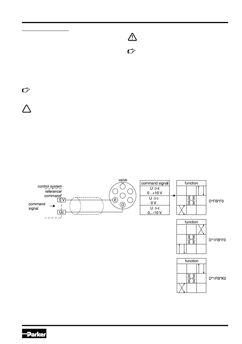
Command signal input:
The command signal for the valve will be connect-
ed to the difference signal input of the electronic
driver. The solenoid current behaves proportional to
the command signal amplitude. Different versions of
command signal processing are available, depend-
ing on the valve type. These are described below:
For the function description is assumed as signal
reference (0V):
Code F0/M0/S0/G0: pin E, Code W5: pin 5
Details are shown from the technical specifi-
cations.
The command input signal needs to be filte-
red as well as free of inductive surges and
modulations. Due to the sensitivity of the val-
ve a high signal quality is recommended, this
will prevent malfunction.
Wiring diagram of voltage command input +10...0...-10 V Code F0/M0 (6 + PE)
 Loading...


