16
Prop. Directional Control Valve
Series D*FB / D*1FB
Operation Manual
Parker Hannifin CorporationParker Hannifin Corporation
D_FB-D_1FB_10-12 5715-669 UK.indd 25.06.19
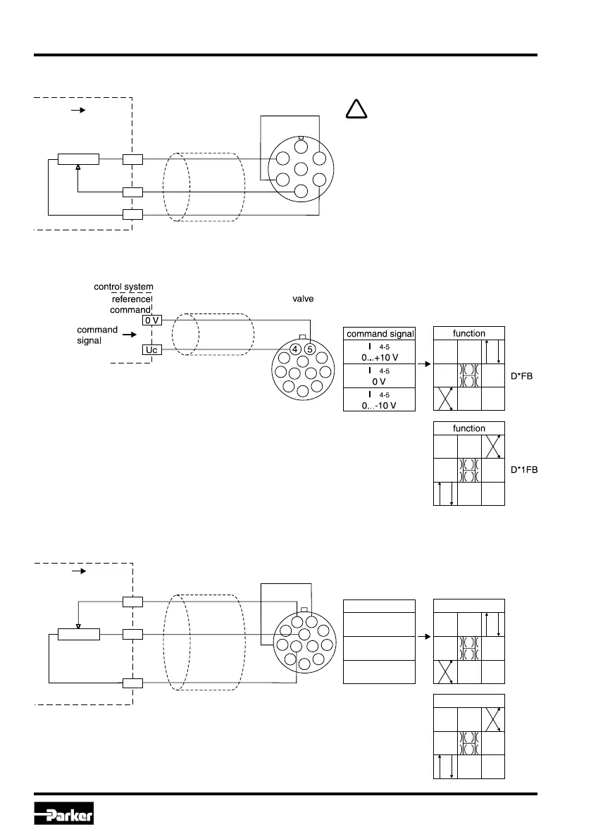
command signal
0...+10 V
U
4-5
0V
U
4-5
0...-10 V
U
4-5
potentiometer
command signal
Uc
-Up
+Up
-10 V
+10 V
5...10 k
4
5
2
10
9
function
D*FB
function
Wiring diagram of voltage command input +10...0...-10 V
Code W5 (11 + PE)
Wiring diagram of voltage command input +10...0...-10 V via potentiometer
Code W5 (11 + PE)
B
C
D
E
F
B
C
A
valve
potentiometer
command signal
Uc
-Up
+Up
-10 V
+10 V
5...10 k
Wiring diagram of voltage command input +10...0...-10 V via potentiometer Code F0/M0 (6 + PE)
The external potentiometer is fed
via the output “potentiometer sup-
ply”. To prevent this output from
overload, the resistance value of
the potentiometer should be within
a range of 5...10 kOhm. A nomi-
nal power rating of 0.1 W is suffi-
cient.
 Loading...


