Prop. Directional Control Valve
Series D*FB / D*1FB
Operation Manual
21
Parker Hannifin CorporationParker Hannifin Corporation
D_FB-D_1FB_10-12 5715-669 UK.indd 25.06.19
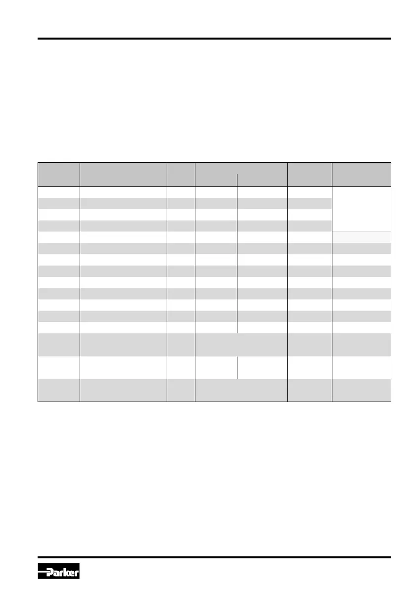
Parameter overview for basic mode
Parameter Description Unit
Parameter Range Default
Setting
Comment
from up to
S1 internal Sollwert S1 % -100 100 0.0
code W5 only
S2 internal Sollwert S2 % -100 100 0.0
S3 internal Sollwert S3 % -100 100 0.0
S4 internal Sollwert S4 % -100 100 0.0
S5 ramp accel. channel A ms 0 32500 0
S6 ramp decel. channel A ms 0 32500 0
S7 ramp accel. channel B ms 0 32500 0
S8 ramp decel. channel B ms 0 32500 0
P3 MAX channel A % 50.0 100.0 100.0
P4 MAX channel B % 50.0 100.0 100.0
P7 MIN channel A % 0.0 50.0 0.0
P8 MIN channel B % 0.0 50.0 0.0
P11 polarity command – 0 1 0
E17 option command –
1 = ±10V
1 = ±10V code W5 only
3 = 4-20mA
E19
cable break detection
command
– 0
0 = ±10V
0 = +/-10V
codes S0 & W5
only
1 = 4-20mA
E25 MIN operating threshold –
0 = 1%
0 = 1%
1 = 0.01%
Adjustment parameters
The available parameters may be divided into
multiple groups and are characterized by different
letters:
S-parameters
P-parameters
E-parameters
 Loading...


