OEM750 •
➁
Installation
29
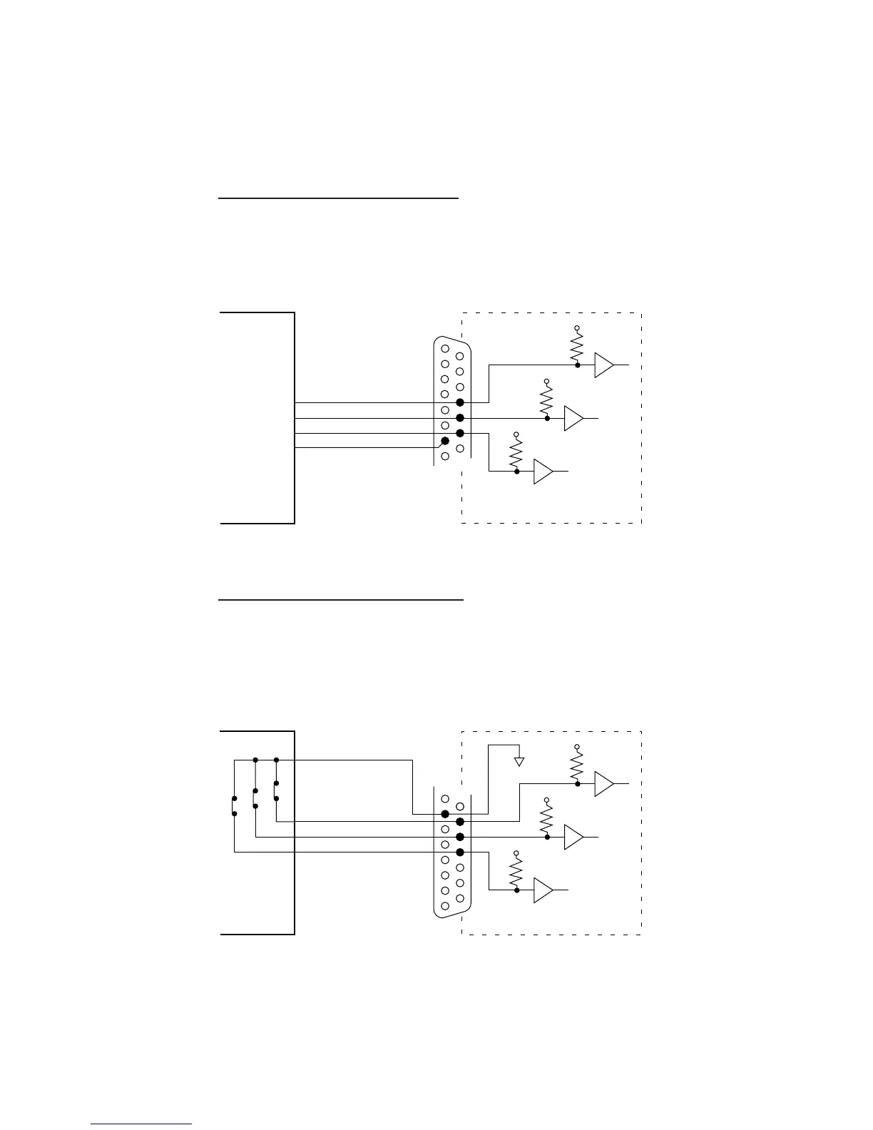
ENCODER INPUTS A, B, Z (PINS 17–19)
The OEM750X has three dedicated inputs for use with a
single ended incremental encoder. These inputs, in conjunc-
tion with the FS commands, determine encoder functionality.
Reference the encoder ground to pin 7 of the OEM750X.
Internal Connections
+5V
4.75KΩ
HCT244
+5V
4.75KΩ
HCT244
+5V
4.75KΩ
HCT244
External Devices
Encoder Channel A
Encoder Channel Z
Encoder Channel B
• Maximum low-level input: 0.8V
• Minimum high level input: 2V
• Maximum encoder frequency: 1.2MHz
14
15
16
17
18
19
20
7
Encoder Ground
Encoder Inputs
TRIGGER INPUTS #1 – #3 (PINS 20 – 22)
The OEM750X has three dedicated trigger inputs. These
inputs are pulled up internally. They can be active high or
active low, depending on how you configure them with the
Trigger (TR) command. The figure represents a typical con-
figuration of these inputs.
Internal Connections
+5V
4.75KΩ
HCT541
+5V
4.75KΩ
HCT541
+5V
4.75KΩ
HCT541
External Devices
Trigger Input #1
Trigger Input #3
Trigger Input #2
• Maximum low-level input: 0.8V
• Minimum high level input: 2V
Normally Closed
Switches
19
20
21
22
23
24
25
6
7
8
9
10
11
12
13
Trigger Inputs

 Loading...


