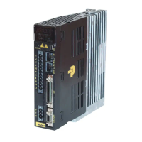
Do you have a question about the Parker PM-FBL04AMK and is the answer not in the manual?
Outlines safety requirements and recommendations for PD drive installation, including enclosure use.
Provides specifications for MCCB, noise filter, DC reactor, MC, and cables for different drive powers.
Details how to set the node address for multiple drives using rotary and toggle switches.
Details the built-in regeneration brake resistor specifications for different drive powers.
Instructions for configuring an external regeneration brake resistor when needed.
Lists and describes the various alarm codes for the PD drive.
Lists and describes the various warning codes for the PD drive.
Outlines the procedure for testing the PD drive after installation, including expected motor behavior.
Provides wiring examples for power, feedback signals, I/O signals, and pulse signals.
Wiring example for the power supply connections to the drive, including notes on terminals and cables.
Wiring diagrams for various encoder feedback signals (Quadrature, Serial, Tamagawa, EnDAT2.2).
Examples of wiring for digital input and output signals, as well as analog signals.
Wiring examples and details for pulse train input signals, including line drive and open collector types.
Explains Modbus command codes like Read Holding Register, Read Input Register, and Write Register.
Lists parameters related to system configuration, including motor ID, encoder type, and regeneration settings.
Lists parameters for controlling servo functions like gains, limits, and P/PI conversion.
Lists parameters for configuring digital and analog I/O signals and their functions.
Lists parameters conforming to the CiA402 standard for motion control.
Parameters for configuring index-based position operations, including control mode and index settings.
Details digital input and output signals, including pin assignments and function descriptions.
Details analog input and output signals, including connections and function descriptions.
Wiring examples and details for pulse train input signals.
Information on how the drive outputs encoder signals in line drive and open collector methods.
Instructions for allocating digital input and output signals to I/O connectors.
Details how to allocate functions to digital input signals and set their signal levels.
Details how to allocate functions to digital output signals and set their output signal levels.
Overview of servo tuning, control modes, and the cascade control structure.
Explains system stability and the consequences of instability, like exponential error increase.
Describes how to automatically set gains based on load conditions using drive commands.
Guides on tuning speed and position controller gains in a specific order for cascade controllers.
Details steps for tuning speed controllers, including inertia ratio, proportion gain, and filter settings.
Explains the conversion between PI and P control based on torque, speed, or error parameters.
Explains the built-in homing function for returning the motor to its origin.
Lists and describes various supported homing methods using limit switches, index pulses, and stoppers.
Explains how to set electronic gear ratios for rotating the motor by a minimum user-defined unit.
Covers setting up speed control, including smooth acceleration/deceleration profiles.
Covers setting up position control, including the use of position command filters.
Covers setting forward/reverse limit signals and stopping the motor using emergency stop.
Explains how to limit the drive's output torque using torque limit functions and values.
Describes jog operation as a function to check motor action by speed control without a host device.
Explains when and how to reset the absolute encoder's multi-turn and single-turn data.
Lists servo alarm codes, their descriptions, and corresponding checklist items for resolution.
Covers the operation of indexing position control, detailing its components.
Explains the basic PTP operation methods for absolute and relative motor movement.
Details functions related to index input signals like Pause, Stop, HSTART, ORG, JSTART, JDIR.
Describes overriding index speed using analog input when operating index position.
Lists objects that conform to the CiA402 standard for motion control.
Provides specifications for PM-FAL and PM-FBL series motors, including power, torque, and speed.
Provides guidance for diagnosing and resolving abnormalities during operation using alarm and warning codes.
Lists servo alarm codes, their descriptions, and corresponding checklist items for resolution.
| Brand | Parker |
|---|---|
| Model | PM-FBL04AMK |
| Category | Servo Drives |
| Language | English |


