Parker Hannifin Corporation
Pneumatic Division
Richland, Michigan
www.parker.com/pneumatics
17
For inventory, lead times, and kit
lookup, visit www.pdnplu.com
Tie Rod and Prole Pneumatic Cylinders
P1F Series
Catalog 0980
Accessories
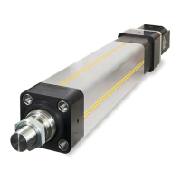
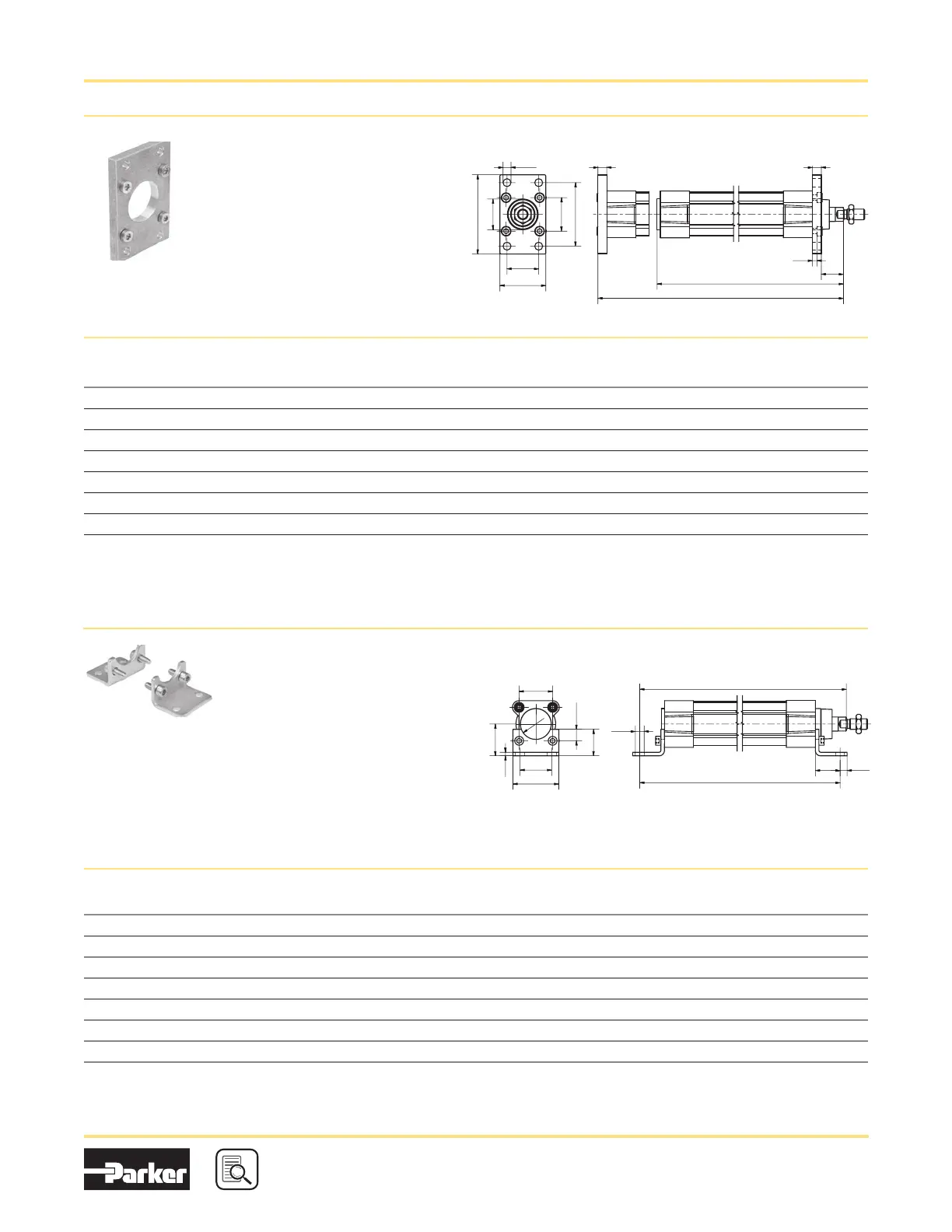
Flange - MF1 / MF2
Intended for fixed mounting of cylinder.
Flange can be fitted to front or rear
end cover of cylinder.
Materials:
Flange: Surface-treated steel
Mounting screws acc. to DIN 6912:
Zinc-plated steel 8.8
Supplied complete with mounting
screws for attachment to the cylinder.
According to ISO 15552
Bore
size
mm
D (H11)
mm
E
mm
ØFB (H13)
mm
L4
mm
MF
mm
R
mm
TF
mm
TG
mm
UF
mm
W*
mm
ZB*
mm
ZF*
mm
Weight
kg Part number
32 30 45 7 5.0 10 32 64 32.5 80 16 123.5 130 0.21
P1C-4KMB
40 35 52 9 5.0 10 36 72 38.0 90 20 138.5 145 0.27
P1C-4LMB
50 40 65 9 6.5 12 45 90 46.5 110 25 146.5 155 0.53
P1C-4MMB
63 45 75 9 6.5 12 50 100 56.5 120 25 161.5 170 0.66
P1C-4NMB
80 45 95 12 9.0 16 63 126 72.0 150 30 17 7. 5 190 1.45
P1C-4PMB
100 55 115 14 9.0 16 75 150 89.0 170 35 192.5 205 1.60
P1C-4QMB
125 60 140 16 10.5 20 90 180 110.0 205 45 230.5 245 3.34
P1C-4RMB
*Does not apply to cylinders with piston rod extension or lock units.
D
U
F
E
MF MF
W+S
ZB+S
ZF+S
T
G
T
F
FB
L4
Ø
R
Ø
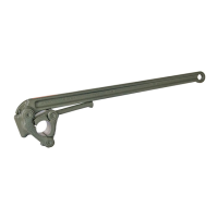
Foot Bracket - MS1
Intended for fixed mounting of cylinder.
Foot bracket can be fitted to front or rear
end cover of the cylinder.
Materials:
Flange: Surface-treated steel
Mounting screws acc. to DIN 6912:
Zinc-plated steel 8.8:
Supplied complete with mounting screws
for attachment to the cylinder.
According to ISO 15552
Bore
size
mm
ØAB (H14)
mm
AH (JS15)
mm
AO
mm
AT
mm
AU
mm
E
mm
L7
mm
R
mm
SA*
mm
TG
mm
TR (JS14)
mm
XA*
mm
Weight
** kg Part number
32 7.0 32 11 4 24 45 30 15.0 142 32.5 32 144 0.08
P1C-4KMF
40 10.0 36 8 4 28 52 30 17. 5 161 38.0 36 163 0.09
P1C-4LMF
50 10.0 45 15 5 32 65 36 20.0 170 46.5 45 175 0.18
P1C-4MMF
63 10.0 50 13 5 32 75 35 22.5 185 56.5 50 190 0.20
P1C-4NMF
80 12.0 63 14 6 41 95 47 22.5 210 72.0 63 215 0.40
P1C-4PMF
100 14.5 71 16 6 41 115 53 2 7. 5 220 89.0 75 230 0.54
P1C-4QMF
125 16.5 90 25 8 45 140 70 30.0 250 110.0 90 270 1.10
P1C-4RMF
*Does not apply to cylinders with piston rod extension or lock units. ** per bracket
A
H
A
T
TR
TG
E
T
G
/
2
L
7
R
AB
AU AO
SA + S
XA + S
Ø
Ø
www.comoso.com