Chapter 3: Starting Your PowerStation PowerStation Connectors
PA PowerStation User Guide 3-7
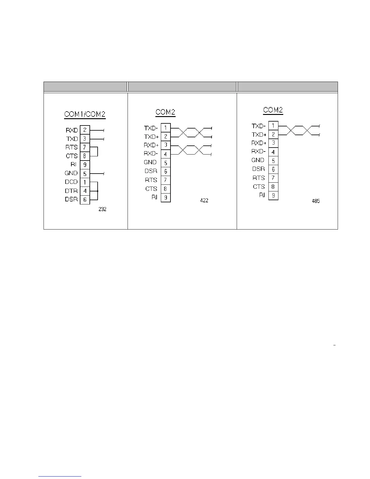
Figure 3-6, displays the connector pinouts and cable wiring required for
communicating with COM1 or COM2 using the RS-232, RS-422 or the RS-
485 protocol. This figure is for the 15” unit only.
Figure 3-6: Connector Pinouts and Cable Wiring on 15” Units
Note: Be careful not to connect any wires to unused connector pins.
RS-485 Directional Control
Many device drivers use the RTS signal to switch between receive and
transmit mode. Some third party communication drivers expect the
directional control to be automatic. The PA PowerStation does not
automatically switch between modes and depends on the driver to use the
RTS signal to perform this operation.
Transferring Files from a PC to the PA PowerStation
You can transfer files from a PC to the PA PowerStation in one of three
ways—through the Ethernet, the CompactFlash, or a Serial Transfer. If you
plan to use a Serial Transfer, you will need a null modem cable. To
construct your own cables, refer to Figure 3-7, for the appropriate settings,
then continue with step 1 below.
RS-232 RS-422 RS-485

 Loading...


