GB IE
12
NI
the product.
Important Instructions
If the motor is overloaded, it switches itself off automatically.
After cooling down (times vary), the motor can be switched on
again.
Faulty Electrical Connection Cable
Insulation damage often occurs to electrical connection cables.
•
windows or door gaps.
•
connection cable.
• Cut surfaces caused by vehicles driving over the connection
cable.
• Insulation damage caused by tearing out of the wall socket.
• Cracks resulting from the insulation becoming old.
Such faulty electrical connections must not be used and may
endanger life due to the damage to the insulation.
Electrical connection cables should be checked regularly for
damage. Ensure that during such checks, the connection cable is
not connected to the mains.
Electrical connection cables must comply with the relevant VDE
and DIN regulations. Only use connection cables with the mar-
king H05VV-F.
It is stipulated by law that the type of connection cable must be
printed on it.
Alternating Current Motor
•
• Extension cables up to 25 m in length must have a cross-sec-
tion of 2.5 mm².
Connections and repairs to the electrical equipment may only be
please provide the following information:
• Current type of the engine
• Data from the machine type plate
• Data from the motor type plate
Assembly
Assembly, Replacement of Parts and Adjustments
Caution! The mains plug must be removed before all
servicing, retooling and assembly work.
the parts which are similar.
Note: If connections are secured with a bolt (round head/or
hexagonal), hexagonal nuts and a washer, the washer must be
placed under the nut.
Insert the bolts from the outside to the inside in each case, secu-
ring the connections with nuts from the inside.
Note:
extent that they cannot fall off.
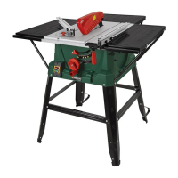
Assembling the frame and table width
extender with length extender
(Figures. 4-13)
2. Insert the four legs (21) at the corner positions into the device
housing. Do not place any screws yet.
3. Now loosely screw the central struts (22) onto the legs (21).
Use the carriage bolts (b), the washers (c), the spring was-
hers (d) and the nuts (e) (Fig. 7).
4. Screw the stand brackets (21) into the rear legs using the
drill holes. Assembly material for each: 2 carriage bolts (b),
the washers (c), the spring washers (d) and the nuts (e)
(Fig. 9). Caution! Both stand brackets must be
attached to the rear of the machine at attachment
points 25! (Abb. 5).
5. Loosely tighten the table width extender (7) and table length
extender (17) on the saw table (1) using the hexagon bolts
table extensions (7) points away from the saw table (1).
6. Loosely tighten the table supports (26, 27) on the housing of
the table circular saw. Use the hexagonal bolts with collar
(a) from bag A. Use the table width extender (7)/table
length extender (17), hexagonal bolts (f), washers (c) and
widening extension, the long supports (27) are for the length
extension, (Fig. 12, 13). Screw the four legs (21) and
the table supports (26, 27) onto the housing.
7.
table.
8. Next, tighten all the screws of the legs (21) and the table
width extender (7)/table length extender (17).
9. Now attach the rubber feet (23) to the legs (21) (Figure 8).
10. .
11. Screw one nut on each of the screws (g). Screw the four
screws with pre-mounted nuts onto the side of the table width
these with four additional nuts. Suspend the collection bag
for wood residues (15) onto the four screws.
Mounting / adjusting the Riving Knife
Insert the battery (Figures 15-20)
Caution! Remove the mains plug! The setting of the
saw blade (4) must be checked whenever a blade has
been replaced.
1. Inserting the batteries (Figure 15):
- Remove the battery compartment cover (38) by loosening the
screw (37). Now remove the battery compartment cover (38)
by bending at the side.
- Insert the batteries supplied (type AAA), ensuring the correct
polarity (see Figure 15).
tighten it with the screw (37). Notes concerning the batteries:
- If you are not going to use the laser for a prolonged period,
please remove the batteries from the battery compartment.