MIC 1400 ManualEdition 1 15
3
2
1
RTD
3
2
1
-
+
Linear (V/mV)
+
-
Linear (mA)
4
16
A
B
17
18
COM
FIGURE 2-10
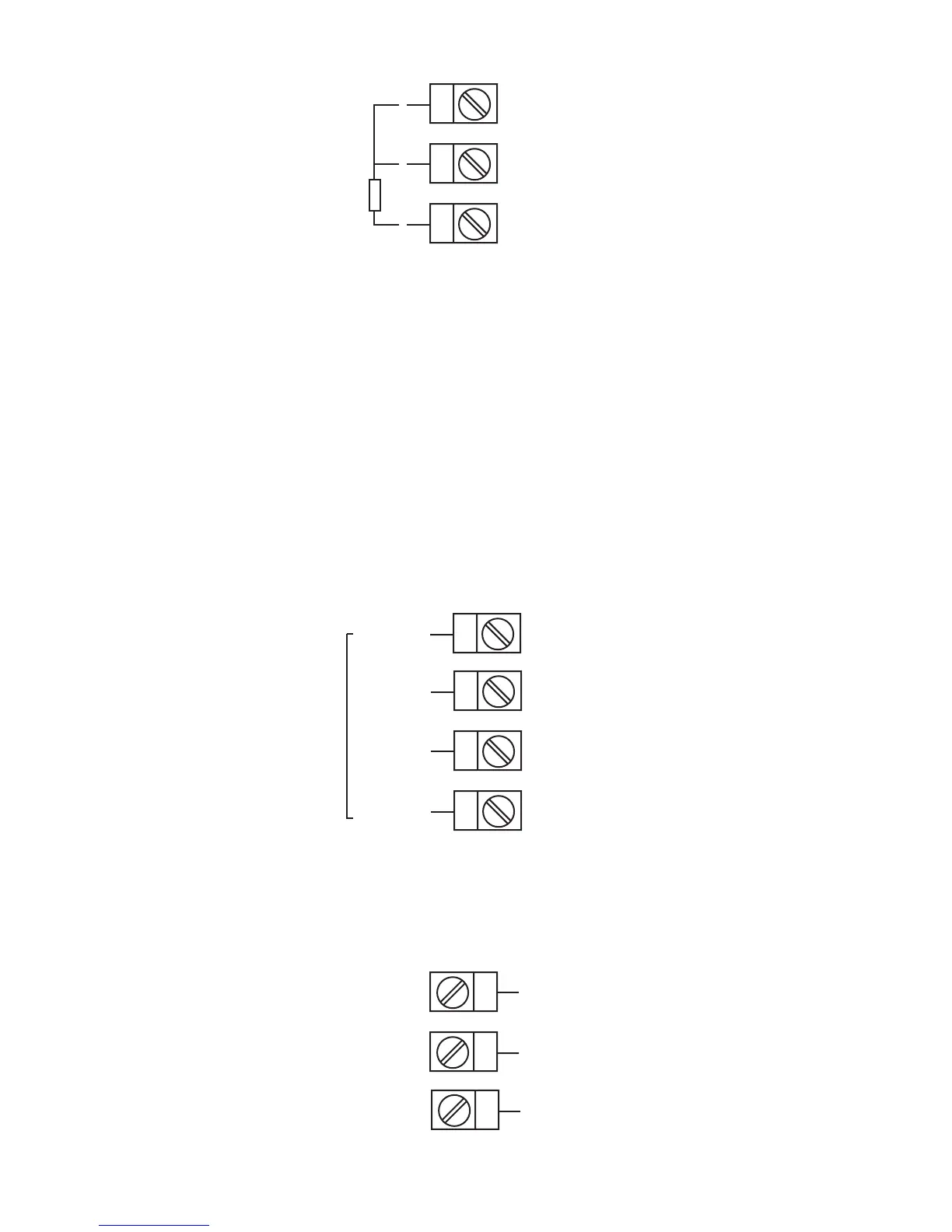
Volt, mV Input
Make volt and millivolt connections as shown below. Terminal 2 is positive
and terminal 3 is negative. Input conditioning jumper must be positioned
correctly (see Appendix B) and Hardware Definition Code must be correct
(see Appendix C).
mADC Input
Make mADC connections as shown below. Terminal 4 is positive and ter-
minal 1 is negative. Input conditioning jumper must be positioned correctly
(see Appendix B) and Hardware Definition Code must be correct (see Ap-
pendix C).
FIGURE 2-11
Remote Digital Communications - RS485
Make digital communication connections as illustrated below.
 Loading...


