www.parweld.com
66
3.0 Technical
Specications
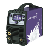
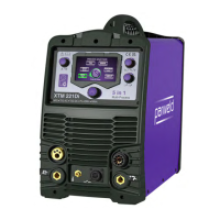
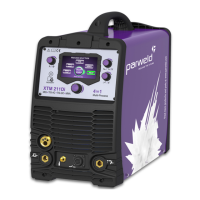
The XTM 211Di, is a compact type machine with integrated wire feed
unit for use with single phase 110/230V supply with smart
input switching.
Process Feature XTM 211Di
Input Voltage 110V+/10% 230V+/-10%
Hz 50/60
Phases 1
KVA 3.7
Generator Size 7 KVA
No-load Voltage (V) 45V
Wire Drive 2 Roll
Fuse Rating (A) 32 16
IP Rating IP23S
Weight (Kg) 27.8
MIG
DC Input Current (A) 39.1 30.0
DC Input eective
Current (A)
21.4 15.0
DC Welding Current (A) 10~140 10~200
Welding Voltage (V) 14.5~21 14.5~24
TIG
DC Input Current (A) 30.5 22.5
DC Input eective
Current (A)
20.5 11.3
AC Input Current (A) 30.5 21.5
AC Input eective
Current (A)
18.0 10.7
DC Welding Current (A) 10~140 10~200
AC Welding Current (A) 10~140 10~200
Welding Voltage (V) 10.4~15.6 10.4~18.8
MMA
DC Input Current (A) 34.9 30.8
DC Input eective
Current (A)
20.6 15.4
AC Input Current (A) 33.8 31.4
AC Input eective
Current (A)
20.0 15.7
DC Welding Current (A) 10~110 10~200
AC Welding Current (A) 10~110 10~200
Welding Voltage (V) 20.4~24.4 20.4~28
Duty Cycle (DC)
110V input 230V input
MIG
30% 60% 100% 25% 60% 100%
140A 105A 80A 200A 160A 140A
TIG
45% 60% 100% 25% 60% 100%
140A 125A 100A 200A 150A 120A
MMA
35% 60% 100% 25% 60% 100%
110A 90A 70A 200A 140A 120A
4.0 Installation
Read entire installation section before starting installation.
SAFETY PRECAUTIONS
• ELECTRIC SHOCK can kill.
• Only qualied personnel should perform this installation.
• Only personnel that have read and understood the Operating
Manual should install and operate this equipment.
• Machine must be grounded per any national, local or other
applicable electrical regulations.
• The MIG power switch is to be in the OFF position when
installing work cable and torch and when connecting other
equipment.
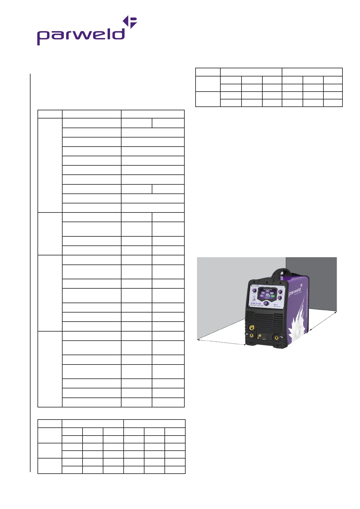
4.1 Location
Position the power source so that its cooling air inlets and outlets are
not obstructed.
A. 100mm (4in.) minimum
B. 100mm (4in.) minimum
4.2 Input and Grounding Connection
WARNING
Before starting the installation, check that your power supply
is adequate for the voltage, amperage, phase, and frequency
specied on the Machine nameplate.
The 110/230 volt 50 Hz machine is supplied with a 3m input cable
and without plug, ensure that you connect a plug that is suitably
rated for the power draw of the machine and the environmental
location.
Have a qualied electrician connect the input plug.
B
A
Duty Cycle (AC)
110V input 230V input
TIG
35% 60% 100% 25% 60% 100%
140A 120A 90A 200A 140A 115A
MMA
35% 60% 100% 25% 60% 100%
110A 85A 70A 200A 140A 115A
 Loading...