www.parweld.com
6
Read and follow instrucons on compressed gas
cylinders, associated equipment, and Compressed Gas
Associaon (CGA)
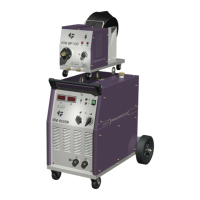
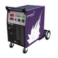
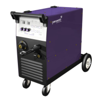
2.0 Product Descripon
The XTM 353SW and 403SW are complete
semiautomac constant voltage DC arc welding
machines built to meet CE specicaons. They
combine a constant voltage power source and a
constant speed wire feeder with a microcomputer-
based controller to form a reliable high-performance
welding system. A simple control scheme, consisng
of a range voltage and wire feed speed controls,
provides versality with ease of use and accuracy.
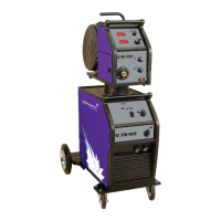
The machines also include built in water cooling and
recirculaon units to allow the use of water cooled
torches. Other features include separate wire feed
unit for remote operaon, an integral gas cylinder
mounng undercarriage, an adjustable Argon ow
regulator with cylinder pressure gauge and inlet
hose, a Parweld MIG torch, and a 3.0m work cable
with clamp. Digital meters display the actual welding
voltage and amperage and the machine has addional
controls for adjustment of burn back and so starng.
3.0 Technical Specicaons
The XTM353SW and 403SW are a separate type
machine with the wire feed unit connected to the
power supply but a 5m interconnecng cable for use
with 3 phase 400V supply.
Feature XTM353SW XTM403SW
Input voltage 400V +/-10% 400V +/-10%
Hz 50 50
Phases 3 3
Current Draw (A) 17.2 18
Fuse rang (A) 18 28
Output current
(A)
60-300 60-400
OCV 18-36 20-45
Load voltage 17-29 17-34
Feed speed m/
min
0.8-24 0.8-24
Feed motor 42V 42V
Wire drive 4 roll 4 roll
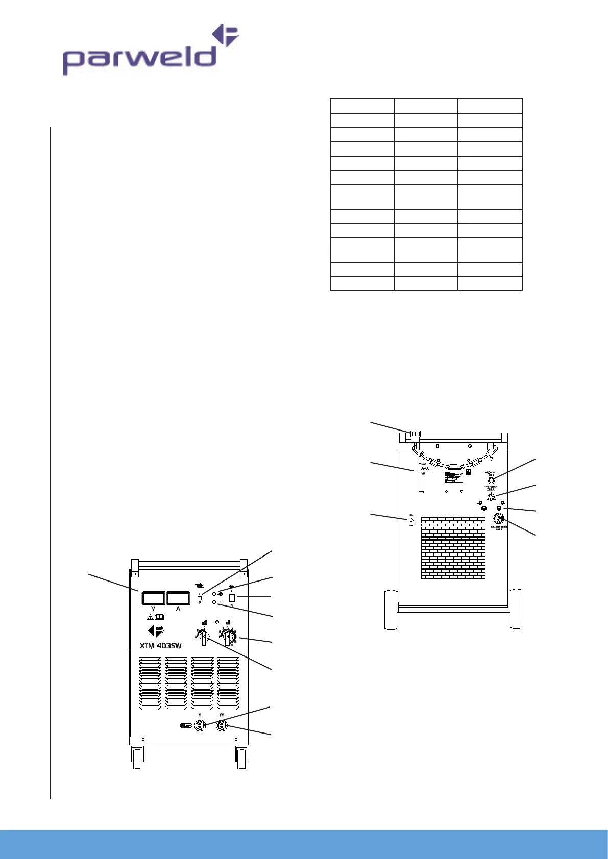
4.0 Descripon of controls
1. Digital display for amperage and Voltage
(displayed real me)
2. Water cooler selector switch. This allows the
water recirculaon pump and the ow switch
to be disabled when an Air cooled torch is
connected.
3. Mains input light This light illuminates when the
mains power is connected and the machine is
switched on.
4. On O switch. The machine is switched o when
the light (4) is o and the fan is not running.
5. Fault light This light will illuminate when a fault or
over temperature condion has occurred. If this
light illuminates allow the machine to cool with
the fan sll running unl it exnguished. If the
light does not go o when the power source has
cooled down then have the machine checked by a
1
2
3
4
5
6
7
8
9
10
11
12
13
14
15
16