www.parweld.com
8
• Only personnel that have read and understood the
Operang Manual should install and operate this
equipment.
• Machine must be grounded per any naonal, local
or other applicable electrical regulaons.
• The MIG power switch is to be in the OFF posion
when installing work cable and torch and when
connecng other equipment.
5.1 Unpacking the Machine
Cut banding and li o cardboard carton. Cut banding
holding the machine to the skid. Remove corrugated
packing material. Remove accessories from Gas Bole
Plaorm.. Roll the machine o the skid
5.2 Locaon
Locate the welder in a dry locaon where there is
free circulaon of clean air into the louvres in the
back and out the front. A locaon that minimizes the
amount of smoke and dirt drawn into the rear louvres
reduces the chance of dirt accumulaon that can
block air passages and cause overheang.
5.3 Input and grounding connecon
WARNING
Before starng the installaon, check that your power
supply is adequate for the voltage, amperage, phase,
and frequency specied on the Machine nameplate.
The 400 volt 50 Hz machine is supplied with a 4m
input cable and without plug, ensure that you connect
a plug that is suitably rated for the power draw of
the machine and the environmental locaon. Have a
qualied electrician connect the input plug. For long
runs over 30m , larger copper wires should be used.
The green/yellow wire in the input cable connects
to the frame of the machine. This ensures proper
grounding of the machine when the machine plug is
inserted into the receptacle.
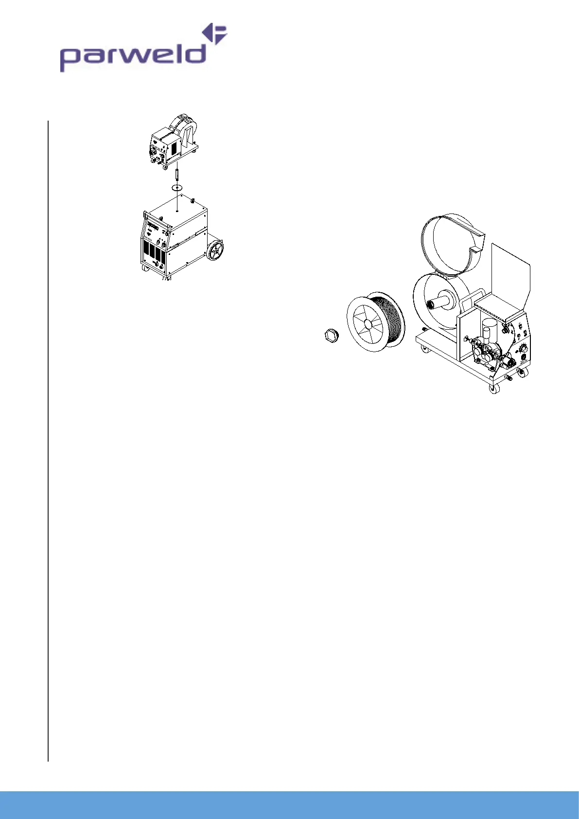
5.4 Assembly of Separate wire feeder
Note:- if the wire feeder is going to be used remotely
to the power source there is not need to assemble the
mounng post.
If the wire feeder is to be used local to the power
source.
Place the at chrome disc over the hole in the top of
the power source lid . Insert the threaded chrome
post thread end rst through the at disc and screw
it securely into the top of the machine. Li the wire
feeder up onto the power source and locate the post
into the tube on the underside of the wire feeder
taking care to ensure it is fully located on the post.
Connecon of the interconnect cable.
Working at the wire feeder end insert the Dinse power
connector and twist it to lock it securely. Connect the
gas hose to the inlet on the rear of the wire feeder
followed by the 4 pin plug taking care to align the pins
before inserng the plug.
At the power source end connect the Dinse socket and
twist to secure, connect the 5 pin control socket taking
care to align the pins before inserng the plug. The
gas hose should be lead o to the outlet connecon of
the gas regulator.