www.parweld.com
9
1. Open the Wire drum cover by pulling down and
out on the boom of the cover
2. Unscrew the plasc retaining wheel from the end
of the spool holder sha.
3. Posion the wire spool so that it will rotate in a
direcon when feeding so as to be de-reeled from
the boom of the coil.
4. Slide the wire spool all the way onto the sha and
ret the plasc retaining nut.
Note:- There is a fricon brake on the reel hub
assembly to prevent the wire spool over running
when welding stops ensure the this is slackened to the
minimum seng. It can be adjusted by means of the
nut visible when the plasc nut is removed.
Fig 1 Fig 2
5.5 Output Polarity Connecons
The welder, as shipped from the factory, is connected for electrode posive
(+) polarity. This is the normal polarity for MIG welding.
5.6 Changing drive roll sets
1. Turn o the power source.
2. Release the pressure on the idle rolls by swinging the adjustable
pressure arm down. Li the cast idle roll assembly and allow it to sit
in an upright posion.
3. Unscrew the plasc knob retaining the lower grooved drive roll and
side o the drive roller.
4. Ensure the wire size marked on the side of the feed roller matches
the wire size to be used.
5. Replace the drive rolls in reverse of the above procedure ensuring the
wire size to be used is marked on the outward facing side of the roller
as it is reed.
NOTE: Be sure that the torch liner and contact p are also sized to match
the selected wire size.
5.7 Welding wire installaon
5. Turn the Spool unl the free end of the electrode
is accessible. While securely holding the
electrode, cut o the bent end and straighten the
rst six inches. (If the electrode is not properly
straightened, it may not feed properly through the
wire drive system Manually feed the wire from
the wire reel and through the wire guide and then
over the top of the wire feed rollers (ensure the
pressure arms are in the raised posion.)
6. Connue to feed the wire through the outlet
guide unl 20mm of wire is protruding from the
front of the machine torch connector.
7. Reposion the adjustable pressure arms to
there original posion to apply pressure. Adjust
pressure as necessary.
Note the pressure arm should be adjusted in order to
give the minimum amount of pressure on the wire to
allow reliable feeding,
5.8 torch installaon
Your Parweld MIG/MAG Welding Torch has been
supplied ready to weld. It has been supplied with
the standard consumables denoted in the product
brochure.
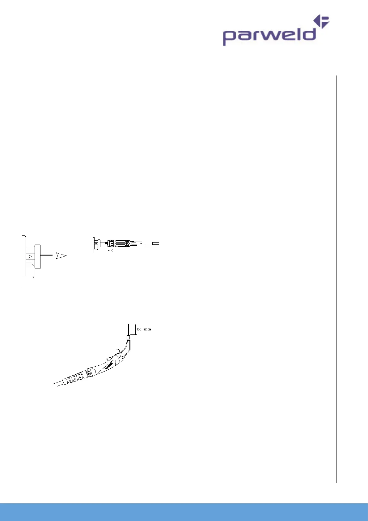
To connect the torch to the power source:-
1. Remove the p adaptor and contact p
2. Inch the wire from the exit of the wire guide on
the feed unit as Figure 1. Ensure that it does not
short out on any machine panels.
3. Carefully slide the electrode wire into the torch
liner and slowly locate the torch gun plug body
into the feed unit central connector and ghten
the gun plug nut as Figure 2
Note; To aid the inial locaon of a new torch and to
prevent damage to the gas nipple O-ring a very light
applicaon of grease to the O Ring is benecial.
4. Keeping the torch as straight as possible, use the
power source inch facility or torch trigger to feed
the electrode wire 50mm from the end of the liner
conduit.
5. Once the electrode wire has stopped, ret the p
adaptor, diuser, contact p and gas nozzle.
6. Trim the electrode wire to within 5mm of the
face of the nozzle, this will facilitate jolt free arc
iniaon.
7. Press the gas purge buon and check the gas ow
is adequate for your applicaon.
8. An inexpensive ow meter is available from
Parweld reference 806001.
9. If you are connecng a water-cooled torch ensure
you have the recommended water ow rate.
Note;- It is essenal to ensure adequate ow of clean,
cool water to prevent irreparable torch failure, a
minimum of 1.2 l/min is recommended.
Parweld recommend the use of its XTS water
recirculaon system designed specically for use with
all water cooled MIG, TIG and Plasma welding torches.
The Parweld XTS recirculaon equipment can be ed
with a fail-safe ow protecon device to prevent