www.parweld.com
7
qualied engineer.
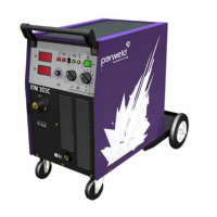
6. Fine Voltage selector switch. This switch is used to
select the require welding voltage each posion of
the switch represents approximately 0.5V. Do Not
operate this switch while welding
7. Coarse Voltage selector switch. This switch is used
to select the require welding voltage each posion
of the switch represents approximately 4V. Do Not
operate this switch while welding
8. Work return lead connecon. This socket allows
connecon of the work return lead to the front of
the machine.
9. Work return lead connecon. High inductance
connecon, this should be used when in spray
transfer mode to give a more stable arc. (Only
ed to XTM403SW)
10. Filling spout for coolant Only use Parweld
Ultracool
11. Coolant level indicator, keep topped up between
min and max.
12. Control circuit protecon fuse
13. Mains input connecon Input connecon for the
pre-installed mains cable
14. Socket for the interconnecon cable to link to the
wire feeder.
15. Water IN/OUT snap connecons
16. Welding power connecon to connect to the inter
connect cable.Protecon fuse for the Auxiliary
output
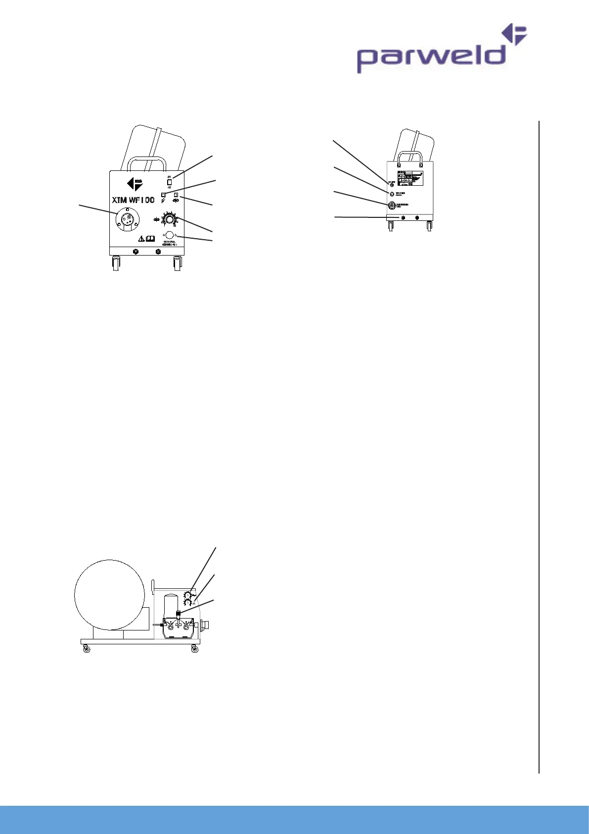
17. 2T 4T, when in the 2T posion the torch trigger
will have a momentary operaon i.e. the welding
operaon will start when the rigger is depressed
and stop when it is released. In the 4T posion a
short press and release of the trigger will start the
welding operaon and a short press and release
with stop the operaon. The 4T mode is ideal for
long welds as it reduces operator fague.
18. Gas purge buon. Pressing this buon allow gas
to ow through the welding torch and so allow
checking of the gas ow before starng the
welding process.
19. Wire inching buon, allows the welding wire to be fed through the
torch without engergising the welding power.
20. Wire feed speed adjustment, controls the speed of wire feeding from
0.8 to 24 m/min. Increasing the wire feed speed also has the eect of
increasing the welding current
21. Locaon for control socket if machine is ed with Push Pull torch
22. Torch connector The Euro connector provided the external
connecon for the welding torch
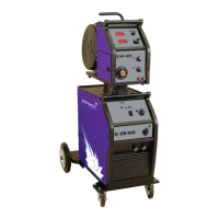
23. So start adjustment which controls the acceleraon of the wire feed
motor when the arc starts to reduce spaer and give a cleaner arc
iniaon.
24. Burn back control aects the wire feed motor over run when the
trigger is released and can be adjusted to ensure that the wire does
not burn back onto the contact p at the end of the weld
25. Pressure adjuster Used to adjust the pressure allied by the feed
rollers on the welding wire.
26. Shielding gas input connecon 3/8 BSP male connecon for the
shielding gas input.
27. Interconnecon cable control socket input
28. Welding power connecon.
29. Water connecons for inter-connect cable
5.0 Installaon
Read enre installaon secon before starng installaon.
SAFETY PRECAUTIONS
• ELECTRIC SHOCK can kill.
• Only qualied personnel should perform this installaon.
17
18
19
20
21
22
23
24
25
26
27
28
29