Inline PSU Tester – User’s Guide Page 12
can control the tester from the software. Moreover, the software allows you to save all
the measurements in a .txt file.
Figure 8
LCD Display
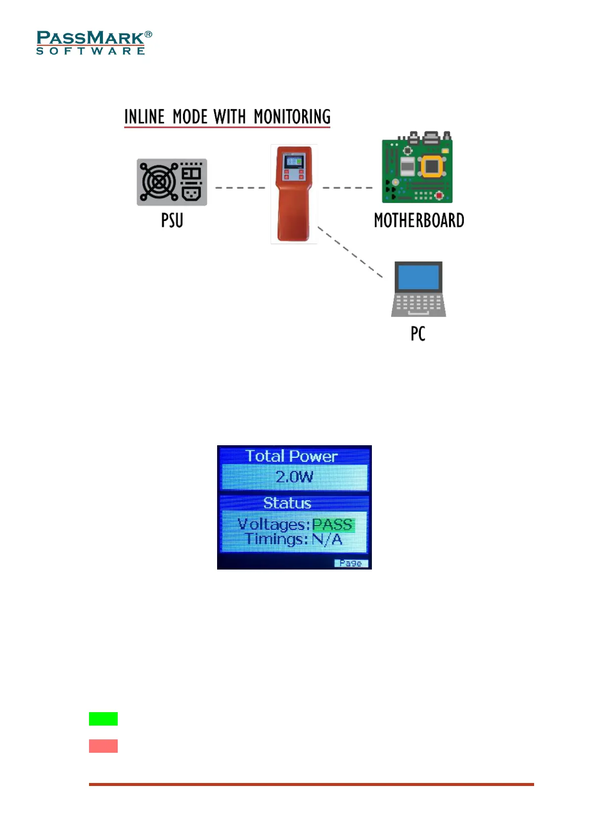
The PassMark PSU Tester features a built-in 1.8” TFT LCD display to show voltage,
current, ripple and power for each voltage rail. The default screen when a device is
connected to a PSU is shown below.
Figure 9
Total Power: Total power drawn by the tester or motherboard.
Voltages: Shows “PASS” when all voltages within the regulation ranges.
Timings: Shows “PASS” when all timings are met. “N/A” means some of the timings
are not yet measured. Timings are calculated during power-up and power-down
process, so if it shows “N/A”, that means one or two power cycles are required to
calculate the timings.
The background colour of PASS/FAIL messages can be green, red, light red and
yellow. Each colour has a different meaning which are explained below:
PASS means voltage is currently within the approved limits and never been outside
the specifications.
PASS means voltage is currently within the approved limits, but an over-voltage was
detected previously.