Inline PSU Tester – User’s Guide Page 9
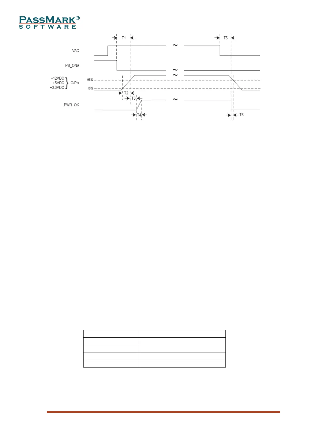
Figure 5
Power-on Time (T1): The power-on time is defined as the time from when PS_ON# is
pulled low to when the +12VDC, +5VDC, and +3.3VDC outputs are within the
regulation ranges. The power-on time shall be less than 500 ms (T1 < 500 ms).
Rise Time (T2): The output voltages shall rise from ≤10% of nominal to within the
regulation ranges within 0.1 ms to 20 ms (0.1 ms ≤ T2 ≤ 20 ms).
PWR_OK delay (T3): PWR_OK is a “power good” signal. It should be asserted high
by the power supply to indicate that the +12VDC, +5VDC, and +3.3VDC outputs are
above the under-voltage thresholds. The PWR_OK time shall be asserted high within
300ms to 500ms after outputs are above the under-voltage thresholds (300 ms < T3 <
500 ms).
Power-down warning (T6): During power-down, the PWR_OK signal should be
asserted low at least 1ms before the +12VDC, +5VDC, and +3.3VDC outputs reach
their under-voltage thresholds (T6 ≥ 1ms).
Ramp up
There must be a smooth and continuous ramp of each DC output voltage from 10% to
90% of its final set-point within the regulation band. The smooth turn-on requires
that, during the 10% to 90% portion of the rise time, the slope of the turn-on
waveform must be positive. The tester monitors the slope and report it as “Positive
Slope”. Also, for any 5ms segment of the 10% to 90% risetime waveform, a straight
line drawn between the end points of the waveform segment must have a slope ≥
[Vout, nominal / 20] V/ms. The tester measures the minimum slope across all 5ms
segments during power-up and displays it as “T2 Min Slew Rate”.