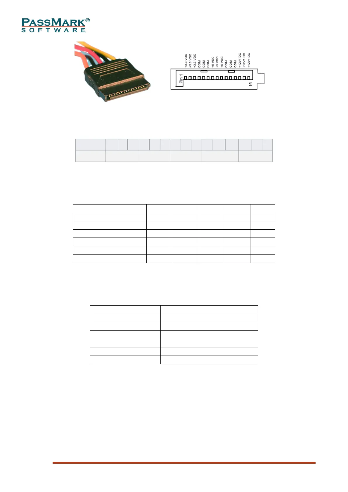
Table 5: 15-pin SATA connector pinout
DC Regulation range
The DC output voltages shall remain within the regulation ranges shown in Table 1.
Table 7
mVpp = Millivolts peak to peak
Timings
Below you can see the timing diagram for the power good signal as available on the
ATX12V specification. “VAC” is the input alternating voltage, i.e., the voltage from
the wall. PS_ON# is the “power on” signal (i.e., you pushed the “standby” button
from the computer case). “O/P’s” stand for “operating points.” And PWR_OK is the
power good signal.