Inline PSU Tester – User’s Guide Page 17
Inline Mode
1. First turn off the power supply by setting the I/O switch on the back panel to
the “O” stand.
2. Disconnect all peripherals and devices from the power supply and connect the
24-pin, 8-pin connector and 6-pin cables of the PSU to the corresponding ‘In’
terminals of the PSU Tester. Note that some power supplies have 8-pin
(6+2Pin detachable) PCIe cable. In this case detach the extra 2 pins and
connect the 6-pin side.
3. Now use the PSU Tester cables to connect “Out” terminals to the motherboard
and PC peripherals (e.g. hard drive and graphic card).
4. Plug the AC power cord into the main
5. Turn on the power supply by setting the I/O switch on the back panel to the
“I” stand.
6. Turn on the machine using the “standby” button from the computer case.
7. Using the Up/Down buttons you can navigate between pages to check the
voltages and timings. By pressing the mode button, you can switch between
voltage, current and power modes or you can see the timing values.
8. If the monitoring port is connected, you can run the monitoring software and
check the PSU parameters from the software as well.
9. You can run BurnInTest during inline testing to ramp up power usage by the
motherboard and place more load on PSU.
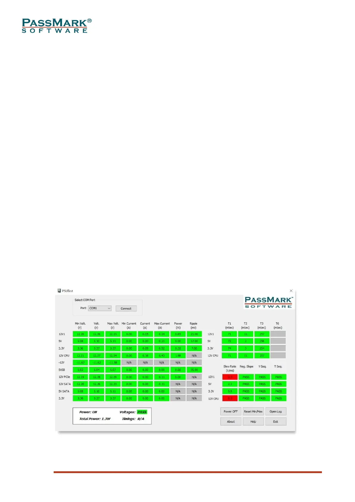
Monitoring Software
The main PSUTest application window is divided into 4 sections: Select COM Port,
PSU Statistics, Overall Status, and control buttons.
Main Window
Figure 16