SmartNode 4131 Overview 17
SmartNode 4131 User Manual 1 • General information
Ports descriptions
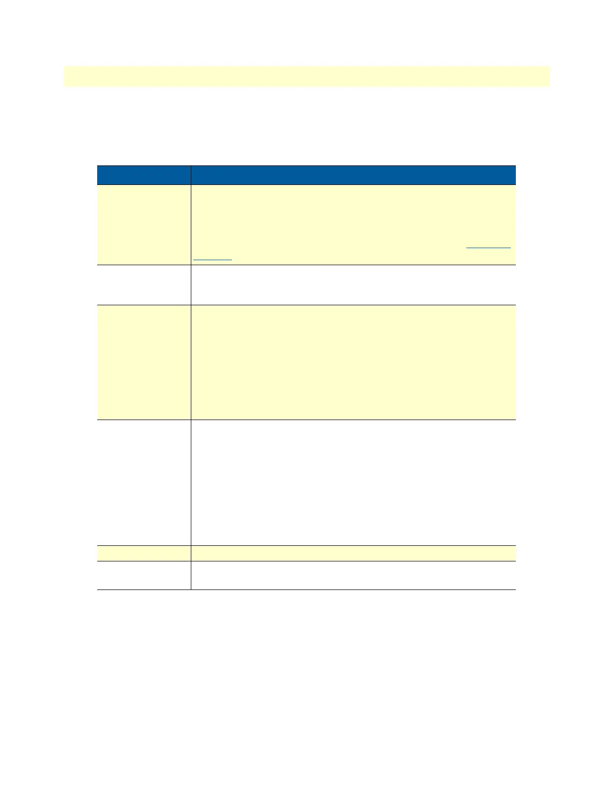
The SmartNode 4131 Series rear panel ports are described in table 2
Table 2. Rear panel ports
Port Description
ETH 0/0 - ETH 0/1 Auto-MDX Fast/Gigabit-Ethernet ports, RJ45 (see figure 2), connects the
unit to an Ethernet WAN device (for example, a cable modem, DSL
modem, or fiber modem).
Note: IP Routing is disabled on SN4131 models. See Software license
options under the accessories tab on the product webpage at
www.pat-
ton.com to enable it.
USB 2.0
USB 2.0 host port (see figure 2 on page 16) to connect a USB 3G/4G
Cellular Modem. A list of supported USB Models can be found in the
release notes and in the Software Configuration Guide
BRI 0/0 - BRI 0/7
ISDN BRI TE/NT port, RJ-45 socket S0/T0 interface (see figure 2 on
page 16), connects the SmartNode with an ISDN device over an S/T bus,
e.g. a PBX or an NT.
The port can be switched between TE and NT mode.
The interface is internally terminated with 100 Ohm.
Point-to-point or point-to-multipoint configurable. If the port is in NT
mode, a Phantom power supply can be switched on to supply connected
phones with power.
Console
Used for service and maintenance, the console port (see figure 2 on
page 16) an RS-232 RJ-45 connector, connects the product to a serial
terminal such as a PC or ASCII Terminal (also called a dumb terminal).
Configuration settings:
• 19200 bps
• 8 bits, no parity
• 1 stop bit
• flow control off
12V DC, 1A
Electricity supply socket (see figure 2 on page 16)
Reset The reset button has several functions, as described in appendix F,
“Reset Button Functions” on page 72.