SmartNode 4131 Overview 18
SmartNode 4131 User Manual 1 • General information
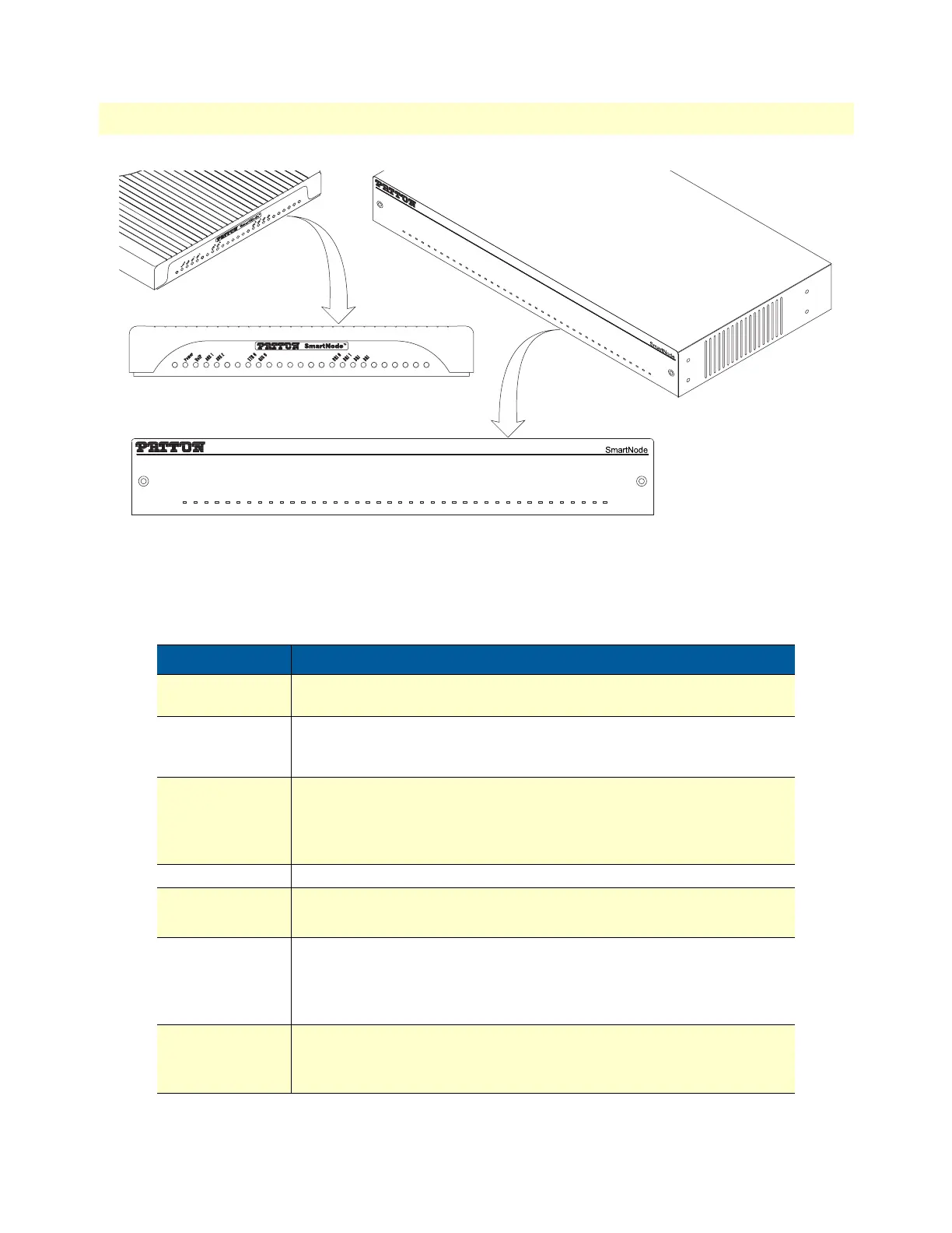
Figure 3. SmartNode 4131 front panels
SmartNode 4131 Front Panel
Figure 3 shows SmartNode 4131 LEDs, the LED definitions are listed in table 3.
Table 3. SmartNode 4131 LED
LED Description
Note: If an error occurs, all LEDs will flash solid for MORE than 5 sec-
onds before the device reboots
Power When lit, indicates power is applied. Blinks fast during bootloader phase
and blinks slow during boot process of Trinity Software. Becomes solid
when the system is up and running.
VoIP • On indicates the gateway is registered to a SIP server, or, a SIP device
has registered to the SN4131.
• Off indicates the unit is not configured or registered, or has no active
direct routed VoIP connection.
AUX 1 – AUX 2 For future use
BRI 0 – BRI 7 • On when L1 and L2 are active. Flashes when there are ongoing calls.
• Off when no line or phone is connected or the port is shutdown.
ETH 0 – ETH1 • On when the Ethernet connection on the corresponding port has a link
indication.
• Flashes when data is received or transmitted at the corresponding
Ethernet port.
GIG 0 – GIG 1 • On when the Ethernet is connected to a 1000Mb network.
• Off when the Ethernet is connected to a 10Mb or 100Mb network or not
connected.
SN4131/4BIS8VHP/EUI
SN4131/8BIS16VHP/EUI
2
3
2
3
P
o
w
e
r
V
o
IP
A
U
X
1
A
U
X
2
E
T
H
0
G
I
G
0
B
R
I
0
B
R
I
1
B
R
I
2
B
R
I
3
B
R
I
4
B
R
I
5
B
R
I
6
B
R
I
7
P
o
w
e
r
V
o
I
P
A
U
X
1
AU
X
2
E
T
H
0
G
I
G
0
B
R
I
0
B
R
I
1
B
R
I
2
B
R
I
3
B
RI
4
B
R
I
5
B
R
I
6
B
R
I
7