Installing the Patton SmartNode Gateway 27
SmartNode 4131 User Manual 3 • SmartNode Installation
Connecting the Power Supply
Do the following to connect the main power to the Model 4131:
Note Do not connect the power cord to the AC Mains at this time.
1. Insert the female end of the AC power supply cable to the mains port (see figure 2 on page 16).
2. Verify that the AC power cord included with your device is compatible with local standards. If it is not,
refer to
“Contacting Patton for Assistance” on page 34 to find out how to replace it with a compatible
power cord.
3. Connect the male end of the power cord to an appropriate power outlet.
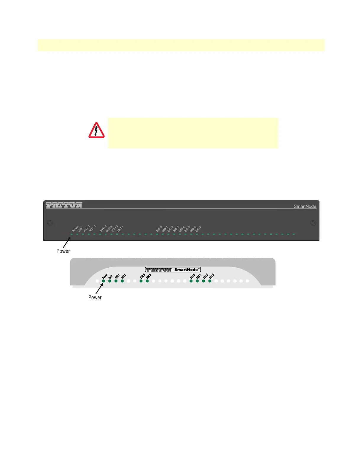
Figure 7. Power LED
4. Verify that the green Power LED is lit (see figure 7).
Note Blinks fast during bootloader phase and blinks slow during boot process of
Trinity Software. Becomes solid when the system is up and running.
Internal S-Bus power supply
The Model 4131 supplies S-Bus line power on the BRI ports that can be activated individually for each port. If
a port is switched to TE mode, line power is switched off. A total of 4W are available.
Congratulations, you have finished installing the SmartNode Gateway! Now go to Chapter 4, “Initial Configu-
ration” on page 28.
There are no user-serviceable parts in the power supply section
of the model SN4131. Contact Patton Electronics Technical
Support at support@patton.com for more information
CAUTION