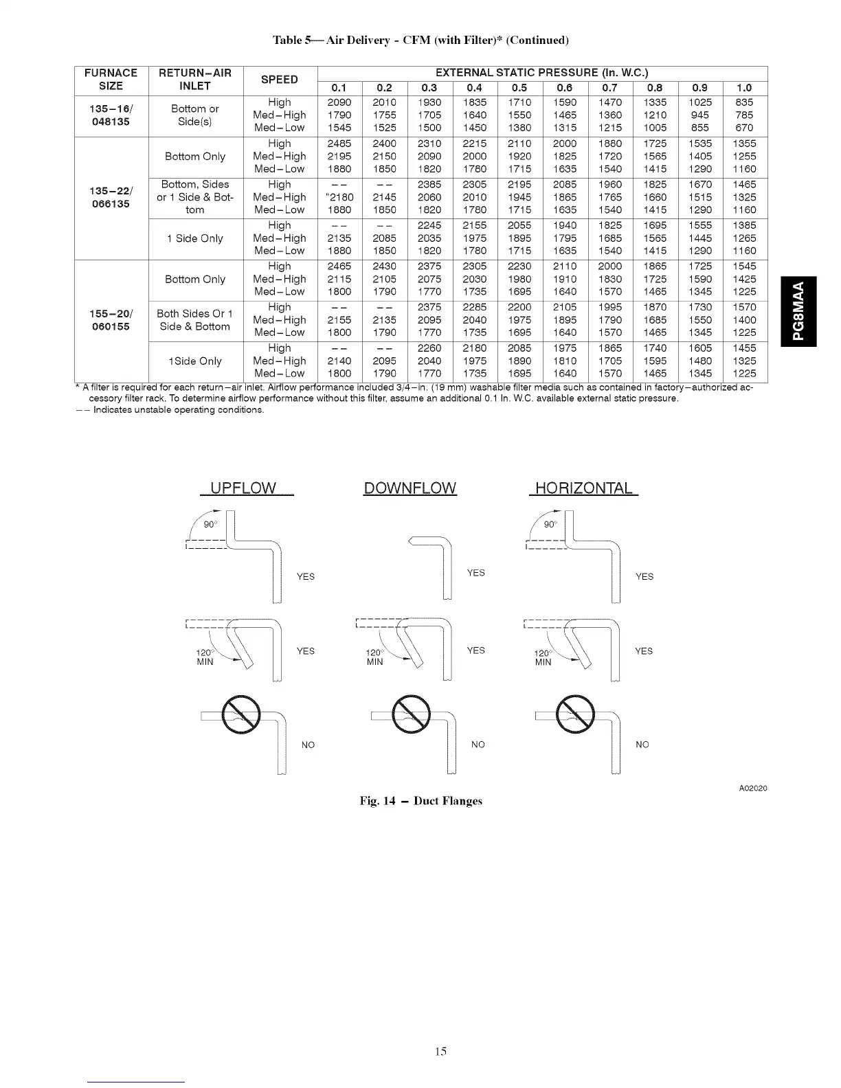
Table 5---Air Delivery - CFM (with Filter)* (Continued)
FURNACE RETURN-AIR SPEED EXTERNAL STATIC PRESSURE (In. W.C.)
SIZE iNLET 0.1 0.2 0.3 0.4 0.5 0.6 0.7 0.8 0.9 1.0
135-15/ Bottom or High 2090 2010 1930 1835 1710 1590 1470 1335 1025 835
048135 Side(s) Med - High 1790 1755 1705 1640 1550 1465 1360 1210 945 785
Med- Low 1545 1525 1500 1450 1380 1315 1215 1005 855 670
High 2485 2400 2310 2215 2110 2000 1880 1725 1535 1355
Bottom Only Med- High 2195 2150 2090 2000 1920 1825 1720 1565 1405 1255
Med - Low 1880 1850 1820 1780 1715 1635 1540 1415 1290 1160
Bottom, Sides High .... 2385 2305 2195 2085 1960 1825 1670 1465
135-22/
066135 or 1 Side & Bot- Med-High "2180 2145 2060 2010 1945 1865 1765 1660 1515 1325
tom Med - Low 1880 1850 1820 1780 1715 1635 1540 1415 1290 1160
High .... 2245 2155 2055 1940 1825 1695 1555 1385
1 Side Only Med-High 2135 2085 2035 1975 1895 1795 1685 1565 1445 1265
Med - Low 1880 1850 1820 1780 1715 1635 1540 1415 1290 1160
High 2465 2430 2375 2305 2230 2110 2000 1865 1725 1545
155-2o/
060155
Bottom Only
Both Sides Or I
Side & Bottom
ISideOnly
Med-High
Med - Low
High
Med-High
Med - Low
High
Med-High
Med - Low
2115 2105 2075 2030 1980 1910 1830 1725 1590 1425
U
1800 1790 1770 1735 1695 1640 1570 1465 1345 1225
.... 2375 2285 2200 2105 1995 1870 1730 1570
2155 2135 2095 2040 1975 1895 1790 1685 1550 1400
1800 1790 1770 1735 1695 1640 1570 1465 1345 1225
.... 2260 2180 2085 1975 1865 1740 1605 1455
2140 2095 2040 1975 1890 1810 1705 1595 1480 1325
1800 1790 1770 1735 1695 1640 1570 1465 1345 1225
A filter is required for each return-air inlet. Airflow performance included 3/4-in. (19 mm) washable filter media such as contained in factory-authorized ac-
cessory filter rack. To determine airflow performance without this filter, assume an additional 0.1 In. W.C. available external static pressure.
-- Indicates unstable operating conditions.
U PFLOW DOWN FLOW HO REZO NTAL
YES
YES
I ......
YES
\
120'_
MIN
/\ /\
YES 120°_ YES 120°_ YES
MIN MIN
NO NO NO
Fig. 14 - Duct Flanges
A02020
15