1/16
[4a_
f_7/8
, --Top OF¢.A_NG
_ 21.6
BOTTOM_T
Q
_B
57/S--
27 @/4
1
--_L ! 1/4
I N_N
A10290
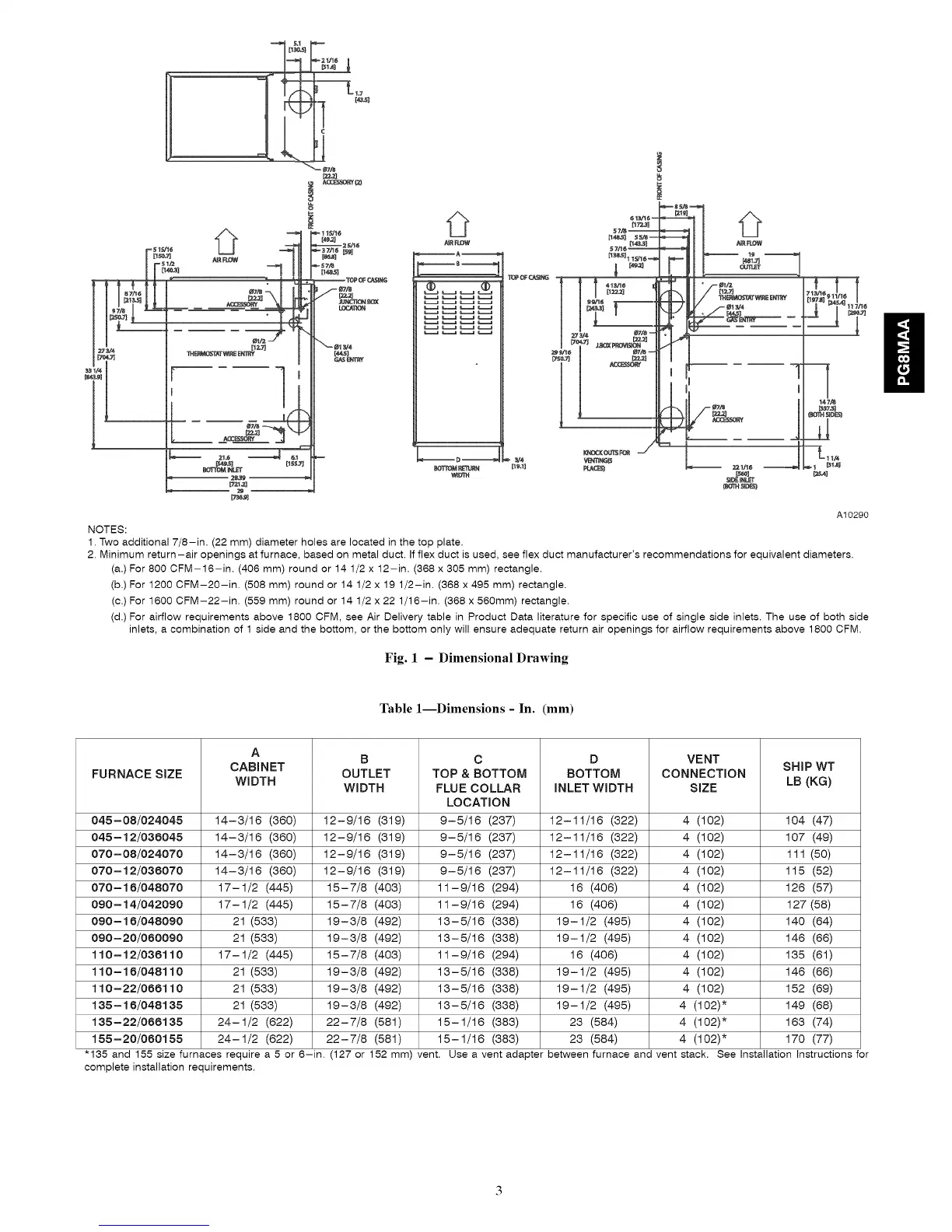
NOTES:
1. Two additional 7/8-in. (22 mm) diameter holes are located in the top plate.
2. Minimum return-air openings at furnace, based on metal duct. If flex duct is used, see flex duct manufacturer's recommendations for equivalent diameters.
(a,) For 800 CFM-16-in. (406 mm) round or 14 1/2 x 12-in. (368 x 305 mm) rectangle.
(b.) For 1200 CFM-20-in. (508 mm) round or 14 1/2 x 19 1/2-in. (368 x 495 mm) rectangle,
(c.) For 1600 CFM-22-in. (559 mm) round or 14 1/2 x 22 1/16-in. (368 x 560mm) rectangle.
(d.) For airflow requirements above 1800 CFM, see Air Delivery table in Product Data literature for specific use of single side inlets. The use of both side
inlets, a combination of 1 side and the bottom, or the bottom only will ensure adequate return air openings for airflow requirements above 1800 CFM.
Fig. 1 - Dimensional Drawing
Table 1--Dimensions - In. (mm)
A
B C D VENT
CABINET SHIP WT
FURNACE SIZE OUTLET TOP & BOTTOM BOTTOM CONNECTION
WIDTH WIDTH FLUE COLLAR INLET WIDTH SIZE LB (KG)
LOCATION
14-3/16 (360) 12-9/16 (319) 9-5/16 (237) 12-11/16 (322) 4 (102) 104 (47)
14-3/16 (360) 12-9/16 (319) 9-5/16 (237) 12-11/16 (322) 4 (102) 107 (49)
14-3/16 (360) 12-9/16 (319) 9-5/16 (237) 12-11/16 (322) 4 (102) 111 (50)
14-3/16 (360) 12-9/16 (319) 9-5/16 (237) 12-11/16 (322) 4 (102) 115 (52)
17-1/2 (445) 15-7/8 (403) 11-9/16 (294) 16 (406) 4 (102) 126 (57)
17-1/2 (445) 15-7/8 (403) 11-9/16 (294) 16 (406) 4 (102) 127 (58)
21 (533) 19-3/8 (492) 13-5/16 (338) 19-1/2 (495) 4 (102) 140 (64)
21 (533) 19-3/8 (492) 13-5/16 (338) 19-1/2 (495) 4 (102) 146 (66)
17-1/2 (445) 15-7/8 (403) 11-9/16 (294) 16 (406) 4 (102) 135 (61)
21 (533) 19-3/8 (492) 13-5/16 (338) 19-1/2 (495) 4 (102) 146 (66)
21 (533) 19-3/8 (492) 13-5/16 (338) 19-1/2 (495) 4 (102) 152 (69)
21 (533) 19-3/8 (492) 13-5/16 (338) 19-1/2 (495) 4 (102)* 149 (68)
24-1/2 (622) 22-7/8 (581) 15-1/16 (383) 23 (584) 4 (102)* 163 (74)
24-1/2 (622) 22-7/8 (581) 15-1/16 (383)
(127 or
045 - 08/024045
045 - 12/036045
070 - 08/024070
070 - 12/036070
070 - 16/048070
090 - 14/042090
090 - 16/048090
090 - 20/080090
110-12/038110
110-16/048110
110-22/088110
135-16/048135
135 -22/088135
155 -20/080155
"135 and 155 size furnaces require a 5 or 6-in.
complete installation requirements.
23 (584) 4 (102)* 170 (77)
152 mm) vent. Use a vent adapter between furnace and vent stack. See Installation Instructions for