Jumper JP10: Fax/Modem Enable/disable
Use this jumper to enable or disable the onboard Fax/Modem.
Disable the Fax/Modem if you plan on using another Fax/Modem.
Function Jumper Setting
Enable Fax/Modem Short Pins 2-3
Disable Fax/Modem Short Pins 1-2
Note: If you have disabled the onboard audio system with
jumper JP8, the Fax/Modem will not function even if it is
enabled.
Install the Mainboard
Install the mainboard into the system chassis. This mainboard uses
the baby-AT format. In addition the mainboard can operate using
an AT power supply unit or an ATX power supply unit. This
means that you have a wide choice of cases that can be used by this
mainboard.
Install the mainboard into the unit case. Follow the instructions
provided by the case manufacturer using the screws and mounting
points provided in the chassis.
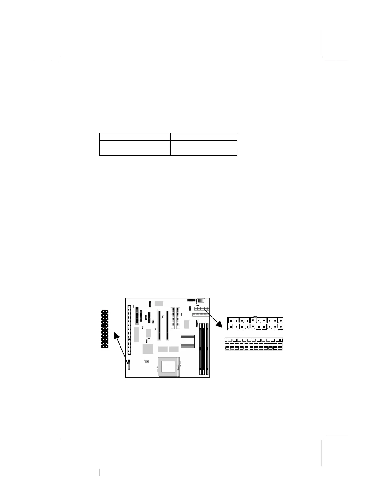
Connect the power cable from the power supply unit to the power
connector on the mainboard. If you are using an AT power unit,
ATX-PWR2
J2
1
AT-PWR1