NMS044 Reference Manual Completing System Assembly 12
c. When the battery is fully charged, disconnect the AC battery charger from
CBL228 as shown in Figure 2-2.
• When the LED on the solar charge controller is blinking green, the battery
is charging.
• When the LED is solid green, the battery is nearly full or fully charged.
• When the LED is dark, ensure the battery is properly installed and the sys-
tem is powered on. For more information, see “
LED Indicators for Solar
Charge Controllers” on page A-4.
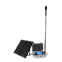
Figure 2-3 Disconnecting the Solar Connectors (CBL228)
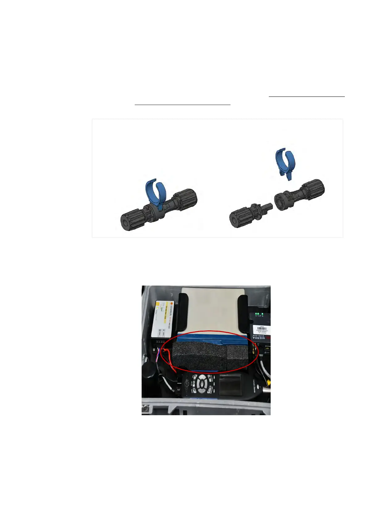
Step 3.
(Optional) If your system included the Sealed Lead Acid battery (BAT020), insert
the included foam spacer (1 x 8 x 5-inches; 2.5 x 20 x 13-cm) to fill the space
between the battery and the 831C SLM.
Figure 2-4 Foam Spacer Placement for BAT020
Step 4.
Place the mounting plate back into the case over the battery until fully seated.
1
2
If you need to disconnect the solar connectors, a tool is provided. 1) Insert the tool
in the middle of the connection 2) pinch the locking mechanism, then pull apart.