NMS044 Reference Manual System LED Indications A-2
System Power Indicators
The system power status is indicated by the green LED behind the SLM power button 0.
Measurement Status Indicators
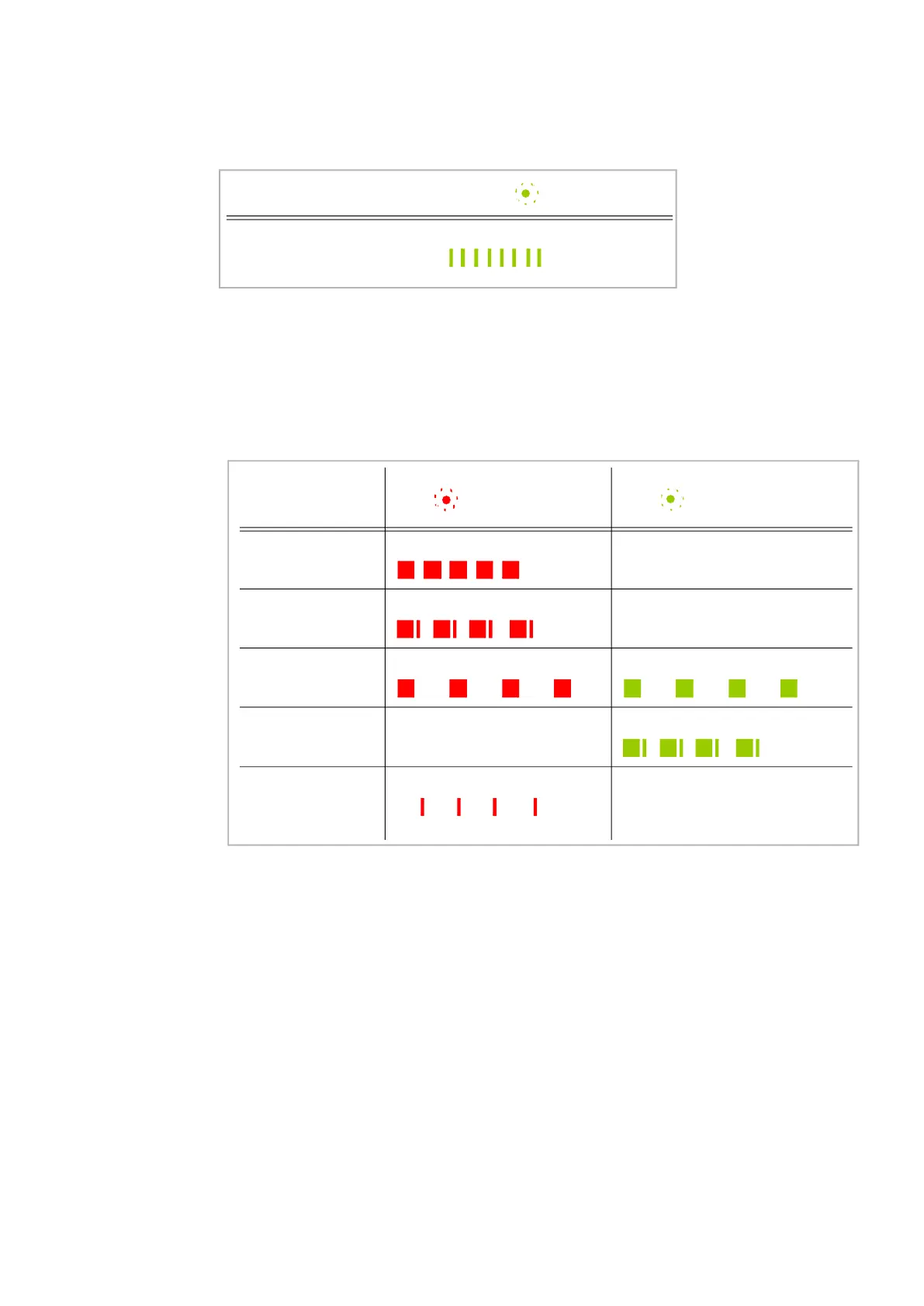
SLM measurement status is indicated by the LEDs behind the Stop button 7 and the
Play/Pause button
9 as shown in Table A.2.
Table A.1 Power Status LED Indicator
Status
0 Green LED
System is powering up or
shutting down
FAST, SHORT GREEN BLINK
Table A.2 Measurement Status LED Indicators
Measurement
State
Red LED
7 Green LED 9
Stopped with
Reset
LONG, QUICK RED BLINK
OFF
Stopped
LONG THEN SHORT RED BLINK
OFF
Paused
SHORT RED BLINK SHORT GREEN BLINK
Running
OFF
LONG THEN SHORT GREEN BLINK
Waiting for valid
data to begin
running
SHORT DELAYED BLINK
OFF