Page 10
Ph: 804.227.3023
10511 Old Ridge Rd. Ashland, VA 23005
v 2.1
Powertrain Control Solutions
5 Verify Operation of Initial Setup
When connected to the TCM, open the monitor screen by selecting the “Monitor” icon on the tool bar. Instructions for
verifying TPS and VSS operation. Reference Figure 17.
Figure 17: Monitor Button
4.2 Throttle Position Setup
Throttle position calibration may or may not need to be done, depending on installation. The most common installations
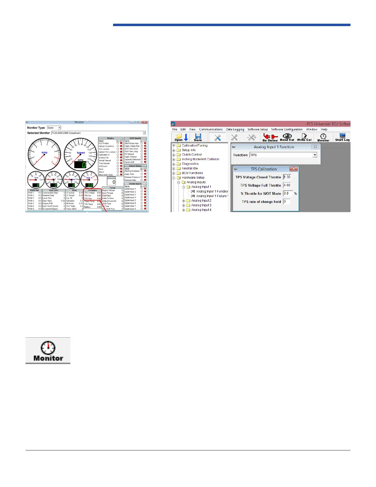
consist of wiring into an existing TPS or supplying the TCM with a dedicated TPS. If set up in this way, the minimum and
maximum voltages of the throttle range must be entered into the calibration. The analog input pin from the TCM will be
wired to the signal output pin of the TPS. The TCM wiring harness provides a +5v reference voltage signal (red wire with
white stripe) and a ground reference signal (black with white stripe). The TPS output pin should increase in voltage as you
open the throttle. A typical closed throttle voltage value is .45v. A typical wide open throttle (WOT) value is 4.5v. After you
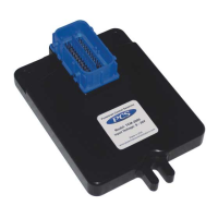
connect the wires you can verify the voltage readings on the TCM Monitor window. Click on the monitor icon or use CTRL
M. when you are online with the ignition on and the engine off you will be able to monitor and record the min voltages at
0 Throttle and Max throttle voltage when you depress the pedal to the oor. Reference Figures 15 and Figure 16.
* If you are using an existing TPS sensor you do not need to connect the 5v reference wire.
*Other types of TPS installations are covered in section (ENTER Section here) of the full manual. At this time, it is recommended to save the calibration
le with a different le name than the original le. You can do this by clicking “File,” then “Save Calibration as…”
Figure 16: TPS Calibration
Figure 15: Monitor Screen, TPS Voltage Range