PCS TCM2800 Quick Start Guide
Page 13
Ph: 804.227.3023
10511 Old Ridge Rd. Ashland, VA 23005
v 2.1
Figure 23: Manual Range Pressure A
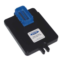
Figure 21: Shift Table A showing shifts from 1
st
to 2
nd
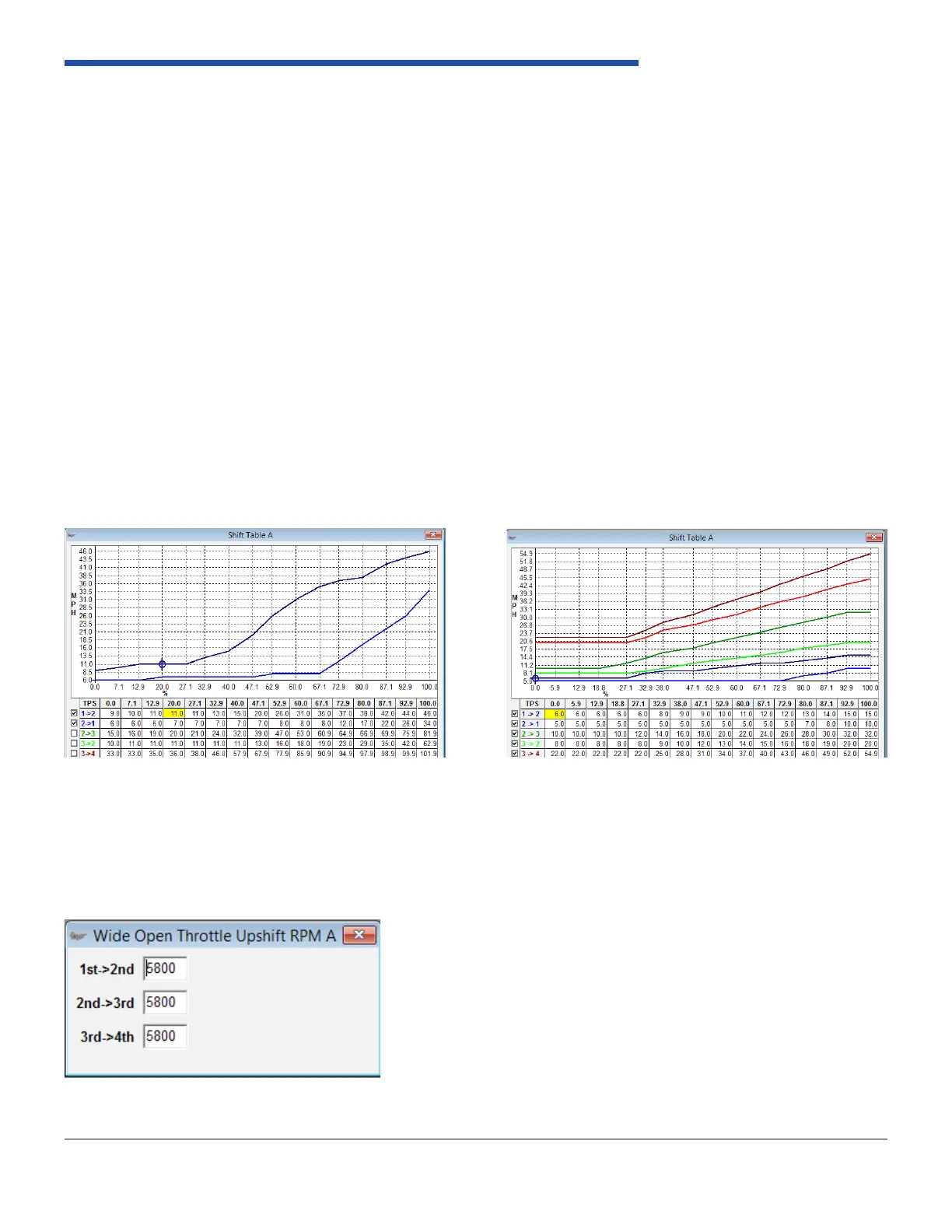
Figure 22: Shift Table A showing all shifts
6.4 Upshift/Downshift Tables
Shift points are determined by MPH (miles per hour) and TPS (throttle position sensor) percent. Open the calibration “A”
folder then the shift points Cal A folder. There is a table, gure X, that when rst opened lets you view all the shift points
for each gear. This table controls the part throttle upshift and downshift parameters for each gear. There is a second set
of tables that are identical to this in the Calibration “B” folder. These give you the option of creating two distinct patterns,
such as Normal and Sport mode or Tow Haul mode etc. Keep in mind while editing this table that the WOT settings, if
enabled, contain your full throttle upshift and downshift parameters and should be matched to these tables. Also keep in
mind that your TPS input must be congured to determine what WOT throttle is.
You will notice that next to the shift lines are boxes with check marks. This lets you choose the shift lines that are plotted
in the chart. For explanation purposes, we have selected Low gear to high gear shift (upshift). A good example to walk
through is pictured in Figure X. The shift table below shows a 1st to 2nd gear shift with a purple line. In most congurations
you will want to use load (TPS or MAP) as an indicator of desired shift speed. At low load you will want a low shift speed
to keep the engine from revving too high. Maintaining a low shift speed will also lead to smoother shifting as line and
accumulator pressure are typically programmed for softer operation at low load. At high load you will want a high shift
speed to utilize full engine power before shifting. Your upshift points (purple line) should always be higher than your
downshift points (blue line). In each cell, the transmission will not upshift until reaching the speed value in the box for
each load point. Be careful not to exceed your maximum RPM with any speed value.
Shift points are determined by MPH (miles per hour) and TPS (throttle position sensor) percent. In the example below,
you will see we are in the Shift Table A, with all the boxes checked. This lets you view all the upshift and downshift lines.
Reference Figure 21 and Figure 22.
6.5 Wide Open Throttle (WOT) Upshift RPM A
There are setting for Wide Open Throttle engines RPMs for both Calibration “A” and Calibration “B”. These are used for
the upshifts only. You can set this to the desired engine RPM per gear. Reference Figure 23.