Page 2
Ph: 804.227.3023
10511 Old Ridge Rd. Ashland, VA 23005
v 2.1
Powertrain Control Solutions
1.4 Connections
1.4.1 Inputs
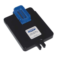
Transmission Control Module (TCM) Connector
The main transmission connector varies depending on the transmission model you are working with. Verify the
connector and wiring diagram match your transmission prior to beginning the installation. PCS harnesses connect
all of the internal transmission solenoids, sensor switches that the TCM requires to control the transmission.
Simply plug it into the connector of the transmission. Reference Figure 1.
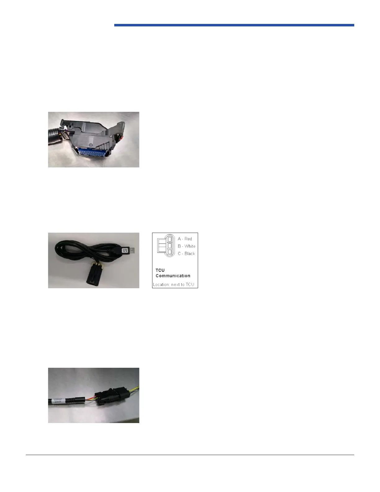
Laptop Calibration Connector
This connector allows the TCM to interface with your laptop. The laptop calibration connector plugs into the
supplied communication cable. Reference Figure 2.
Throttle Position Sensor (TPS)
Throttle position is required for all transmissions to function properly.. There is a three wire connector used for
the throttle position sensor. Typically, the mating connector has 2 wires, Yellow and Black for the TPS reference
signal and black and white for the analog sensor ground. This is typically the AD1 input under the Digital Input
setup. Reference Figure 3.
Figure 3: Throttle Position Sensor (TPS)
Figure 2: Laptop Calibration Connector
Figure 1: TCM Connector