PCS TCM2800 Quick Start Guide
Page 3
Ph: 804.227.3023
10511 Old Ridge Rd. Ashland, VA 23005
v 2.1
RPM Wires (unterminated)
There are 2 wires in the harness that are used for the RPM input. There Orange and Black for the RPM signal and the
Black and White for RPM Ground. This signal will need to be congured. This wire is not required for operation of your
TCM-2800 unit but it is recommended to offer comprehensive diagnostic capabilities. To utilize the full diagnostic function
of your TCM-2800, connect this wire to the tachometer output wire of your ignition system. The TACHOMETER GROUND
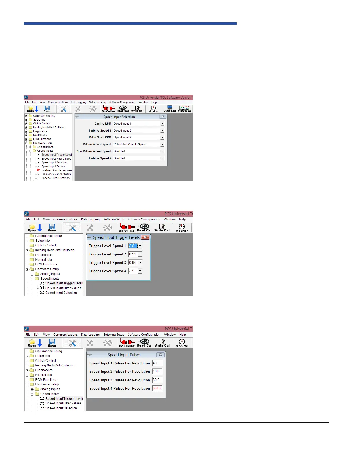
wire must also be connected in the Hardware Setup, there are 4 windows that are used to congure this input. The Speed
Input Selection is precongured for Speed 1, since this is what the standard harness utilizes. Reference Figure 4.
The “Speed input Trigger Value” for speed 1, needs to be set to the signal input value from your engine management
system. Reference Figure 5.
The settings for “Speed Input 1 Pulses Per Revolution”, need to be congured. The value for this will depend on what type
of input you are using to monitor Engine RPM. Reference Figure 6.
Figure 6: Speed Input Pulses
Figure 5: Speed Input Trigger Levels
Figure 4: Speed Input Selection