Page 4
Ph: 804.227.3023
10511 Old Ridge Rd. Ashland, VA 23005
v 2.1
Powertrain Control Solutions
CAL A/B Wire
This single wire is one of the unterminated digital inputs that can be used to enable a secondary calibration, Such
as Sport mode. This gives you the ability to create a completely separate shift map and pressure tables for use as a
sport or tow mode. This lead can be attached to a switch that will enable it when pulled low (Grounded) to change to a
completely different calibration. When it is not activated the default position (off) will be the Cal A setting. When switched
on (grounded), the TCM will change to operate from the Cal B calibration.
Cancel Overdrive
When enabled this cancels gear ratios over a 1:1 ratio (overdrive). In automatic transmissions this is almost always the
highest gear.
4WD Low
When enabled, this acts as an output speed divisor. This is for 4WD applications where the transfer case and the speed
output are connected to the output of the transmission. Without any correction, this would cause the speedometer to
read abnormally high. The correction factor enabled by this digital input must be programmed in the gear ratio tables. This
input should be wired to the 4WD low button or (if lever activated) to the 4WD low sensor in the transfer case or shift lever.
Dyno Mode
When enabled, this mode will allow you lockup the torque converter and choose a gear for dynamometer use. Locking
up the torque converter will lower transmission loss and may increase power numbers on the dyno. Typically you will
want to choose a gear that is 1:1 to use for the dyno as this gear ratio usually has the smallest amount of loss in the
transmission. Both parameters are congurable. All upshifts/downshifts will occur at the value specied by 0% TPS in the
upshift/downshift tables. Upshifts will occur until reaching the desired gear specied in the dyno mode form. TCC lockup
will occur based on the speed set in the dyno mode form.
Manual Mode
When enabled, this setting allows the user to upshift or downshift with the press of a button. An analog multiplexed
steering wheel input or two digital inputs may be used for the upshift and downshift commands.
Upshift
This digital input will issue an upshift command to the TCM. This command is only effective when in manual mode.
Downshift
This digital input will issue a downshift command to the TCM. This command is only effective when in manual mode.
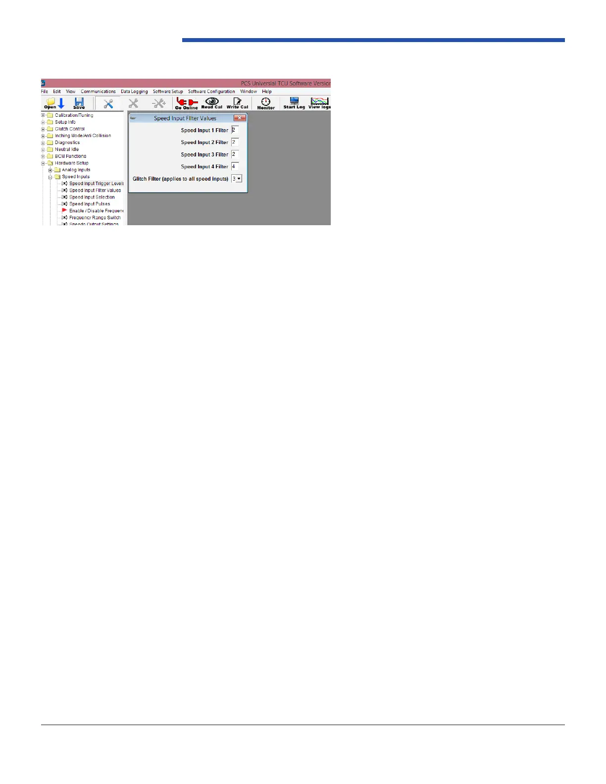
The “Speed Input Filter Values” settings lters will assist in receiving a stable signal. Reference Figure 7.
Figure 7: Speed Input Filter Values