PDI-P20LCD User Manual
Document Number: PD196-040 Rev4
- 5 -
INSTALLATION
LOCATION GUIDELINES
The model PDI-P20LCD Hospital Grade LCD TV is a specialized LCD television. This TV is
intended for entertainment and educational purposes for use in a hospital, a nursing home, a
medical-care center, or a similar health-care facility in which installation is limited to a non-
hazardous area in accordance with the National Electrical Code, ANSI/NFPA 70.
The PDI-P20LCD is capable of being mounted with several commercially available mounting
brackets utilizing the 100 mm VESA hole pattern. The PDI-P20LCD TV is able to be wall
mounted at the foot of a patient’s bed with the supplied bracket. Select a location that is near a
AC wall outlet and that does not expose the TV to bright room lights or sunlight if possible. The
LCD TV also requires connection of both CATV cable signal and across-room wiring for the pillow
speaker.
OSHPD (State of California Only)
The combined weight of the PDI-P20LCD TV, wall mount, and power supply totals less than 20
pounds. At the time of this writing, the involvement of a written, submitted, reviewed, and
approved plan by OSHPD is not required to install the PDI-P20LCD TV in the state of California.
CABLE SYSTEM GROUNDING
The coax cable system connected to the PDI-P20LCD TV should be grounded in accordance with
the National Electrical Code, ANSI/NFPA 70. The code provides guidelines for proper grounding
and, in particular, specifies that the cable ground shall be connected to the grounding system of
the building, as close to the point of the cable entry as practical.
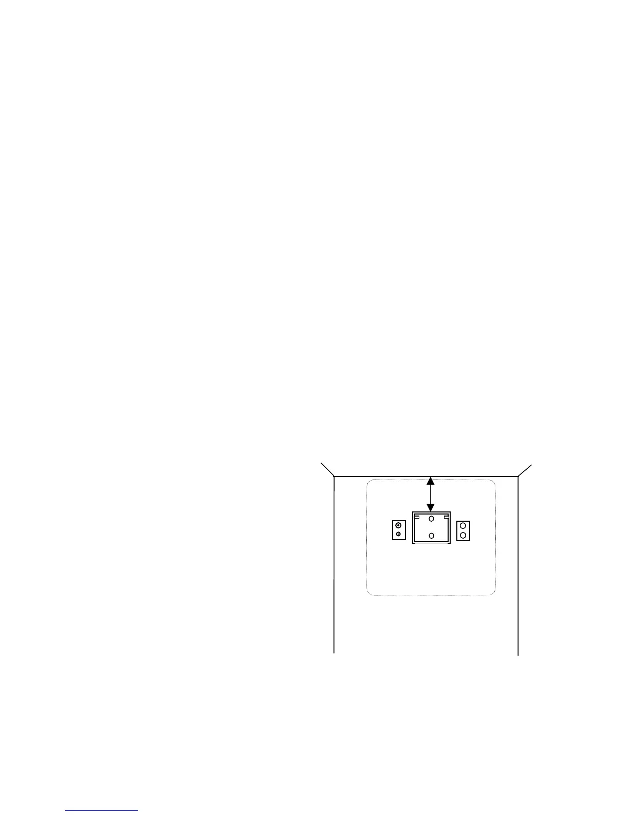
WALL MOUNTING THE LCD TV WITH THE SUPPLIED BRACKET
1. Select a location on the wall
approximately 9 inches below the
ceiling. Position the Wall Bracket and
locate two mounting holes. Secure the
bracket to the wall (mounting hardware
is not included).
2. Position the Back Mount on the LCD
TV cabinet. Attach with four M4
screws provided.
3. Mate the Back Mount to the Wall
Bracket making sure the pivot bolts are
retained in the “L” shaped slot.
Secure with two 10x32 pilfer screws.
4. Slide the Power Pack into the metal
holster. Connect the DC Power Plug
into the “DC 15V” connector on the
back of the TV.
Connect the AC line cord.
5. The TV’s tilt can be adjusted by
loosening both Pilfer Screws, adjusting
tilt, and then tighten.
9”
Wall Bracket
NOT TO SCALE
C
CABLE
CROSS-ROOM
WIRING
P20LCD 20” Vert x 23” Horiz