PDI-P20LCD User Manual
Document Number: PD196-040 Rev4
- 9 -
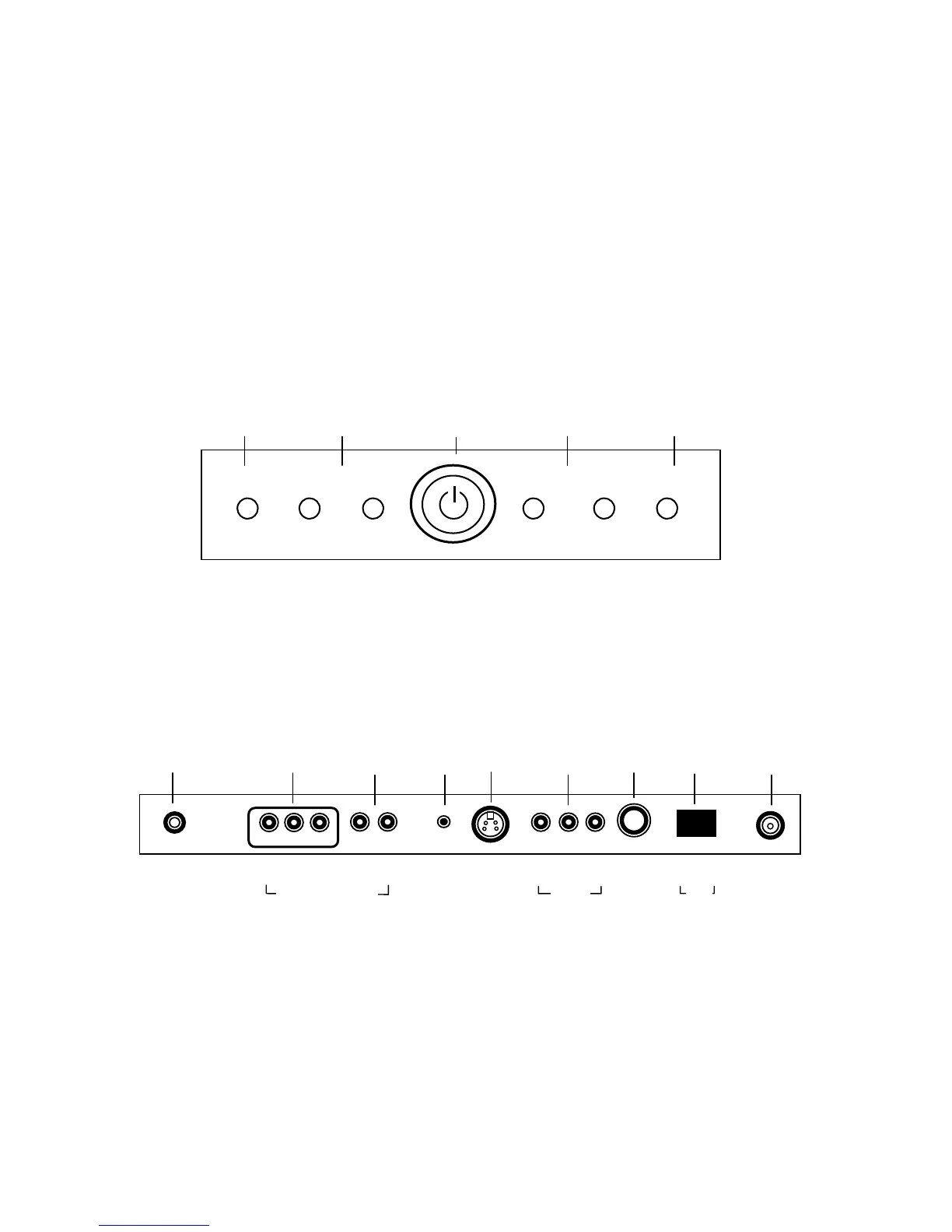
Controls
1. MENU – Displays on-screen menu. The MENU button can be disabled using the remote
control to prevent patient and visitor tampering – see the “Special” menu and “Lock”
instructions elsewhere in this manual for details.
2. ▼CH ▲ – Selects a TV channel or a MENU item when the on-screen menu is active.
3. POWER – Turns the TV On and Off. Illuminates red when the TV is Off. Illuminates
green when the TV is On. Flashes when an IR remote control signal is detected by the
TV.
4. ◄ VOL ► - Adjusts the internal TV speaker or external pillow speaker volume up or
down. Also adjusts a selected menu item when the on-screen menu is active.
5. TV/AV – Selects either TV, COMPONENT, VIDEO, or S-VIDEO. The TV/AV button can
be disabled using the remote control to prevent patient and visitor tampering – see the
“Special” menu and “Lock” instructions elsewhere in this manual for details.
Connections
Connection Panel
The connection panel is located on the back of the TV below the back wall mount and provides
connections to external equipment.
1. DC 15V – Connection point for the external power supply.
2. COMPONENT IN – Component video input.
3. L R – Component audio input.
4. H/P – Stereo Headphone output.
5. S-VIDEO – S-Video input.
6. A/V IN – VCR video and audio input.
7. PILLOW – Digital pillow speaker output.
8. SPK – On Off switch for the internal TV speakers and H/P jack.
9. ANT. – CATV RF cable input.
▼ CH ▲ ◄
OL ►MENU
TV/A
1 2 3 4 5
1 2 3 4 5 6 7 8 9
0 I
▲
ANT.
▲
S-VIDEO
▲
H/P
▲
PILLOW
▲
DC 15V
▲ ▲
OFF ON
▲ ▲ ▲
VIDEO L(MONO) R
▲ ▲ ▲
Y CB CR
▲ ▲
L R
COMPONENT IN
/V IN
SPK