EasyManuals Logo

Peavey CS 1200 User Manual

Peavey CS 1200
12 pages
To Next Page IconTo Next Page
To Previous Page IconTo Previous Page
Page #2 background imageLoading...
Page #2 background image
INSTALLATION
AND
CONNECTION
The
Peavey
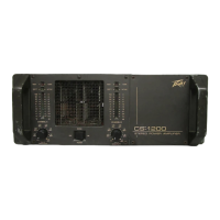
CS-1200
Commercial
Series
Power
Amplifier
is
designed
for
durability
in
commercial
installations
and
the
quality
of
performance
required
instudioand
home
applications.
The
CS-1200
is
adual-channel
power
amplifier
capableof
delivering
more
than
600
watts
RMS
per
channel
intoa4ohm
load
continuously
(both
channels).
The
unit
is
of
thestandard
19"
rack
mount
configuration
requiring
7"
rack
height
and
is
cooled
by
an
automatic
two-speed
internal
fan.
All
inputs
and
outputs
are
on
the
back
panel.
The
front
panel
contains
various
LED
indicators
for
power
output
level,
DDT
activation
and
thermal
shutdown,
detented/'calibrated
sensitivity
controls
and
a
heavy-duty
mains
power
switch.
Mains
Power
Source
The
CS-1200
is
fitted
with
a
single
heavy-duty
#14
AWG,
three-conductor
line
cord
and
a
conventional
AC
plug
with
aground
pin.
It
should
be
connected
to
an
independent
circuit
capable
of
supporting
at
least
20
amps
continuously
or
greater.
This
is
particularly
critical
for
sustained
high
power
applications.
If
the
socket
used
does
not
have
a
ground
pin,
a
suitableground
lift
adaptor
should
be
used
and
the
third
wire
grounded
properly.
Never
break
off
the
ground
pin
on
the
CS-1200.
The
use
of
an
extension
cord
should
be
avoided,
but
if
necessary,
always
use
a
three-wire
type
with
at
least
a
14
AWG
wire
size.
The
use
of
a
lighter
wire
will
severely
limit
the
power
capability
of
this
amplifier.
Always
use
a
qualified
electrician
to
install
any
necessary
electrical
equipment.
To
prevent
the
risk
of
shock
or
fire
hazard,
always
check
to
see
that
the
amp
is
properly
grounded.
NOTE:
The
CS-1200
could
cause
a
15
amp
circuit
breaker
to
trip
during
turn-on.
Industrial
and
Commercial
Installations
For
commercial
and
other
installations
where
sustained
high
power
operation
is
required,
the
amplifiers
should
be
mounted
in
a
standard
19"
rack
It
is
not
necessary
to
leave
rack
space
between
each
amplifier
in
the
stack
since
the
fan
pulls
air
in
from
the
rear
and
exhausts
the
hot
airout
the
front.
An
adequatecool
air
supply
must
be
provided
for
the
amplifiers
when
rack
mounted.
The
internal
fan
must
have
a
source
of
air
that
is
not
preheated
by
other
equipment.
The
amplifier
will
start
up
in
low
speed
fan
operation
and
will
normally
stay
at
low
speed
operation
unless
sustained
high
power
operating
levels
were
to
occur.
Then
as
the
amplifier
heat
sinks
heat
up,
the
automatic
thermal
sensing
circuitry
will
cause
high
speed
operation
to
occur.
Depending
upon
signal
conditions
and
amp
loading,
high
speed
fan
operation
may
continue
or
it
may
cyclo
continuously
between
high
and
low.
This
situation
is
quite
normal.
If
cooling
is
inadequate
dueto
preheated
air
or
a
reduction
of
air
flow
occurs
due
to
blockage
of
the
amplifier
inlet/outlet
ports
or
if
the
amplifier
is
severely
overloaded
or
short-circuited,
then
the
amplifier
thermal
sensing
system
may
cause
temporary
shutdown
of
that
particular
channel.
This
is
indicated
by
the
illumination
of
the
front
panel
high
temperature
LED.
Depending
upon
available
cooling
air,
operation
should
be
restored
in
that
channel
relatively
quickly.
In
any
event,
corrective
action
should
be
taken
to
determine
the
cause
of
the
thermal
shutdown.
If
the
amplifier
is
not
severely
overloaded
or
shorted
and
airflow
is
normal
in
and
out
of
the
amplifier,
then
steps
should
betaken
to
providea
cooler
environment
for
all
the
amplifiers.
As
a
general
rule,
the
cooler
electronic
equipment
is
operated,
the
longer
its
useful
service
life.
You
have
invested
in
the
finest
equipment
that
money
can
buy,
and
a
little
care
will
insure
long
and
reliable
operation.
Portable
Rack
Mount
Applications
Dueto
the
weight
of
the
CS-1200,
we
highly
recommend
that
additonal
support
be
provided
at
the
back
panel
of
the
amplifier
whenever
one
or
more
units
are
installed
in
a
portable
rack
mount
configuration.
For
this
purpose,
two
/>-20allen
head
bolts
(19)
have
been
provided
at
the
rear
of
the
CS-1200.
These
bolts
should
be
attached
to
a
suitable
bracketing
arrangement
to
provide
this
additional
support.
Also,
two
guards
have
been
provided
on
the
rear
panel
of
the
CS-1200
to
protect
connectors,
PL
cans,
and
provide
a
means
for
routing
cables.
CAUTION:
These
are
not
handles
and
they
should
not
be
used
to
lift
the
unit.
Input
Connections
All
input
connections
are
made
at
the
rear
panel.
The
two
'A"
jacks
marked
Power
Amp
Input
(15)
are
wired
in
parallel
for
ease
of
connecting
to
each
channel.
The
dual
(parallel)
jacks
allow
daisy-chaining
to
additional
channels.
If
RCA-type
pin
jacks
are
required,
a
suitable
adaptor
can
be
used
Shielded
cables
must
be
used
to
minimize
hum
and
noise
pickup.
The
nominal
input
impedance
is
20K
ohms.
This
impedance
represents
a
bridging
load
totheassociated
driving
equipmentand
is
compatible
with
the
load
requirementsof
most
home
stereo
devices.
The
CS-1200
has
an
input
sensitivity
of
1.4V
RMS
(+3
dBV)
for
rated
output
with
the
front
panel
sensitivity
control
set
at
full
clockwise,
again
allowing
complete
compatibility
in
home
applications.
This
sensitivity
rating
increases
as
the
control
is
turned
counter¬
clockwise.
The
new
sensitivity
rating
is
indicated
by
the
setting
of
the
calibrated
sensitivity
control.
It
is
generally
wise
to
operate
the
sensitivity
control
at
its
full
clockwise
setting.
The
sensitivity
control
is
discussed
in
greater
detail
later
in
this
manual.
Output
Connections
Two
types
of
output
connectors
are
provided
on
the
rear
panel
of
the
amplifier.
Two
standard
V"
phone
jacks
wired
in
parallel
(17)
and
one
set
of
5-way
binding
posts
(18)
are
available
from
each
channel.
Due
to
the
high
currents
at
full
output
(greater
than
13
amps
RMS),
it
is
recommended
that
#16
AWG
or
larger
wire
size
be
used
whenever
possible.
For
extremely
long
runs
(30'
or
greater),
#14
AWG
should
be
used.
Smaller
wire
sizes
will
waste
power
and
yield
less
than
optimum
results
at
the
speaker.
It
is
suggested
that
in
commercial
and
other
non-portable
applications,
the
5-way
binding
posts
(18)
be
used
instead
of
the
VT
phone
jacks.
The
binding
posts
are
industry
standard
and
mating
banana
plugs
are
available
at
most
electronic
distributors
As
with
any
electronic
equipment,
proper
phase
of
the
outputs
is
a
necessity.
A
little
ti
me
spent
correctly
identifying
the
wi
ring
can
save
a
lot
of
problems
in
the
field.
The
CS-1200
has
a
continuous
rating
of
600
watts
RMS
into
4
ohms.
Music
power
operation
into
2
ohms
should
be
considered
normal
and
generally
will
not
present
any
problems.
However,
continuous
operation
under
these
conditions
might
cause
thermal
shutdown,
depending
upon
cooling
air
temperature.
Operating
into
loads
below
2
ohms,
although
safe
because
of
electronic
protection
mechanisms,
should
be
avoided.
OPERATION
The
CS-1200
commercial
series
power
amplifier
is
designed
for
maximum
ease
and
flexibility
of
operation.
When
the
unit
is
installed
and
connected
as
described
in
the
previous
sections,
operation
is
as
simple
as
turning
on
the
mains
switch
(5)
and
turning
up
the
sensitivity
controls
(1)
to
full
clockwise
setting,
and
then
ad|usting
the
associated
mixer
or
preamplification
equipment
to
supply
the
necessary
signal
levels
to
provide
the
desired
output
level
or
until
the
front
panel
DDT
active
LED
indicator
shows
that
theamplifier
is
compressing.
Further
increases
in
signal
levels
beyond
this
point
will
not
produce
any
significant
increase
in
output
and
could
cause
distortion
problems.

Other manuals for Peavey CS 1200

Questions and Answers:

Question and Answer IconNeed help?

Do you have a question about the Peavey CS 1200 and is the answer not in the manual?

Peavey CS 1200 Specifications

General IconGeneral
Channels2
Signal to Noise Ratio> 100 dB
Input Impedance20k ohms balanced, 10k ohms unbalanced
Weight35 lbs
Dimensions3.5" H x 19" W x 15.25" D

Related product manuals