EasyManua.ls Logo

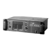
Peavey CS 400x - Channel B Crossover Module and Outputs; Crossover Module Receptacle; Crossover Low Output; Crossover High Output

Peavey CS 400x
16 pages
To Next Page IconTo Next Page
To Previous Page IconTo Previous Page
Loading...
CROSSOVER
MODULE
RECEPTACLE
(15)
This
receptacle
only
receives
a
PL-MODULE
ELECTRONIC
CROSSOVER.
The
PL-
MODULES
are
optional
accessories
and
are
available
in
many
different
crossover
frequencies.
Some
modules
contain
special
equalization
and
special
padding
for
a
particular
Peavey
speaker
enclosure.
Always
be
sure
to
select
the
correct
module
for
your
speaker
system.
Other
special
purpose
modules
are
also
available
for
usage
in
this
receptacle.
.As
such
this
receptacle
supplies
both
the
input
and
output
patch
facilities
and
the
power
supply
"feeds”
for
these
active
elec¬
tronic
devices.
CROSSOVER
LOW
OUTPUT
(16)
This
jack
supplies
the
crossed-over
low
frequency
output
from
the
installed
PL-MODULE
ELECTRONIC
CROSSOVER.
This
output
must
be
patched
to
the
appropriate
power
amp
input
jack
to
‘'create”
an
operational
biamp
system.
On
some
special
purpose
modules,
this
output
jack
is
not
used.
CROSSOVER
HIGH
OUTPUT
(17)
This
jack
supplies
the
crossed-over
high
frequency
output
from
the
installed
PL-MODULE
ELECTRONIC
CROSSOVER.
This
output
must
also
be
patched
to
the
appropriate
power
amp
input
jack
to
create
an
operational
biamp
system.
SPEAKER
OUTPUTS
(18)
Same
function
and
comments
as
channel
A.
MODE
SWITCH
(19)
This
switch
is
used
to
select
either
STEREO
or
BRIDGE
mode
of
operation.
DDT
SWITCH
(20)
This
switch
is
used
to
cither
ENABLE
or
DEFEAT
the
DDT
compressor.
CIRCUIT
BREAKER
(21)
This
breaker
is
provided
to
limit
the
current
to
the
associated
power
transfermer
and
protect
it
from
overheating
and
possible
destruction
due
to
fault
conditions
in
the
amplifier.
The
trip
current
values
have
been
carefully
chosen
to
allow
continuous
power
output
performance
while
still
protecting
the
power
transformer.
Normally,
these
breakers
should
not
trip
unless
there
is
a
fault
in
the
amplifier
circuitry
thal
draws
excessive
mains
current
However,
abnormal
conditions
such
as
a
short
circuit
on
either
or
both
channels,
or
continuous
operation
at
overload
or
clipping
(especially
into
impedance
below
the
impedance
selector
switch
setting
per
channel
and
twice
tfte
impedance
selector
setting
in
bridge
mode)
will
cause
the
breaker
to
trip.
If
this
occurs,
turn
the
power
switch
off.
then
simply
reset
the
breaker
and
correct
the
cause
of
the
overload.
A
When
tripped,
the
button
on
the
breaker
will
he
outward
nearly
1/2'
and
can
be
reset
by
pushing
inward.
A
normal
reset
button
length
is
about
1/4”.
If
this
"thermal"
type
breaker
docs
trip,
simply
pushing
the
button
back
in
will
reset
it.
after
waiting
a
brief
period
of
time
to
allow
it
to
cool
down.
REMEMBER,
ALWAYS
TURN
THE
POWER
OFF
BEFORE
RESETTING
THE
BREAKER.
If
the
breaker
trips
instantly
each
time
you
attempt
to
reset
it.
the
unit
should
be
taken
to
a
qualified
service
center
for
repair.

Related product manuals