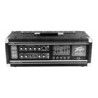
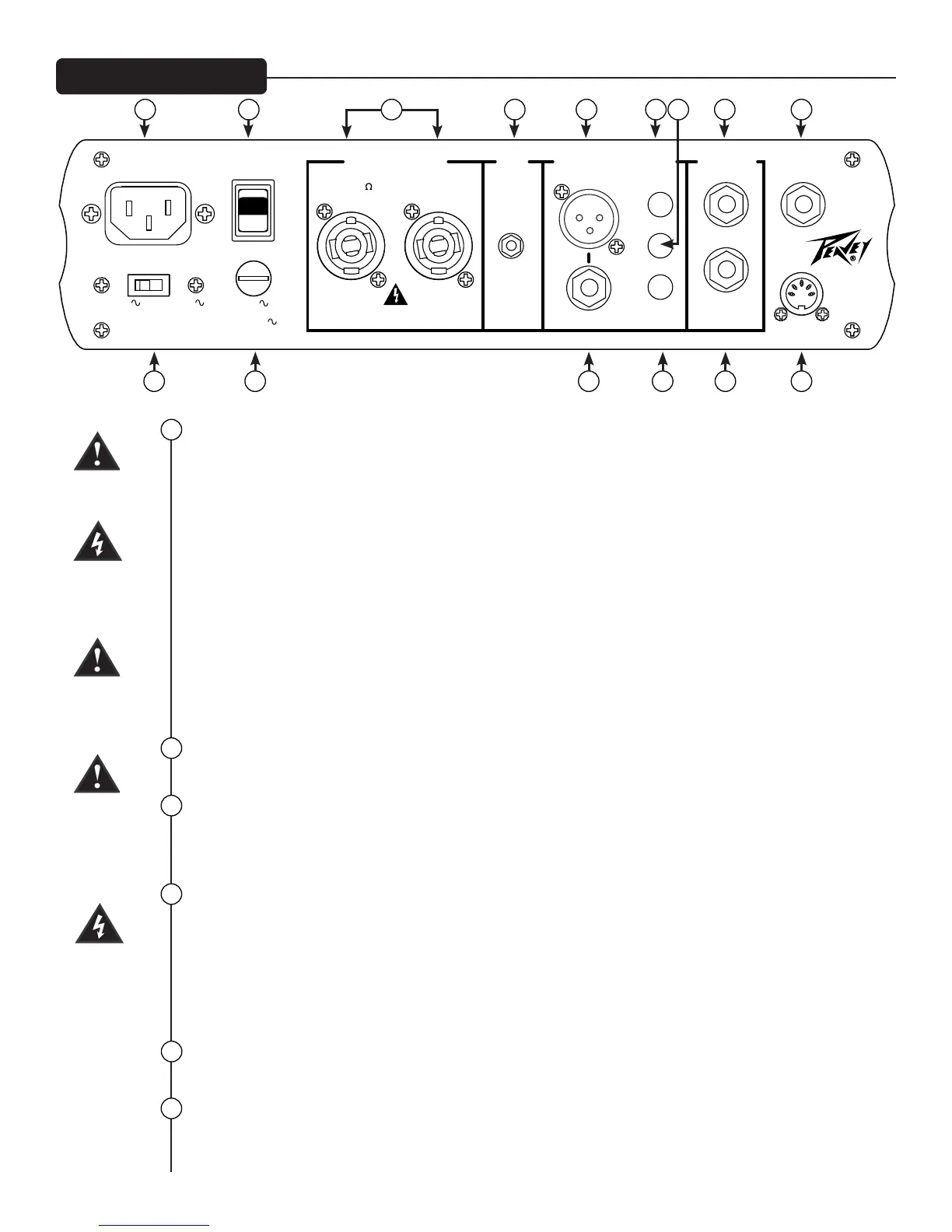
Rear Panel Layout
PRE/
POST
DIRECT INTERFACE
SPEAKER OUTS
AUX
IN
FX LOOP
PAD
ON
GRND
LIFT
SEND
POWER
RETURN
D.I. OUTPUTS
TRS (BALANCED)
TUNER
TM
FOOTSWITCH
SPEAKER JACKS PARALLELED
4 MIN 63.2V RMS
1000W RMS 4 OHMS
CLASS 2 WIRING
50/60 Hz 150 WATTS
120V 220-240V
FUSE
FOR 220-240V OPERATION, FUSE
MUST BE CHANGED TO T5AH/250V
FOR 120V OPERATION, FUSE
MUST BE CHANGED TO T10AH/250V
Consumo de energia 150Wh
220-230V
T5AH/250V
120V
T10AH/250V
mini
MEGA
18 19 22 23 24 26 27 29 31
20 21 25 28 30 32
18
19
20
21
22
23
AC POWER INLET
is is the receptacle for an IEC line cord, which provides AC power to the unit. Connect the line cord to this
connector to provide power to the unit. Damage to the equipment may result if improper line voltage is used. (See
line voltage marking on unit).
Never break o the ground pin on any equipment. It is provided for your safety. If the outlet used does not have a
ground pin, a suitable grounding adapter should be used, and the third wire should be grounded properly. To pre-
vent the risk of shock or re hazard, always make sure that the amplier and all associated equipment is properly
grounded.
NOTE: FOR UK ONLY
As the colors of the wires in the mains lead of this apparatus may not correspond with the colored markings
identifying the terminals in your plug, proceed as follows: (1) e wire that is colored green and yellow must be
connected to the terminal that is marked by the letter E, or by the Earth symbol, or colored green or green and
yellow. (2) e wire that is colored blue must be connected to the terminal that is marked with the letter N, or the
color black. (3) e wire that is colored brown must be connected to the terminal that is marked with the letter L,
or the color red.
POWER SWITCH
Placing this switch into the ON position will provide power to the amplier.
LINE VOLTAGE SELECTOR SWITCH
is selector switch allows the amplier to be operated at dierent voltages. Please be sure this is set to the proper
voltage for your area before turning the amplier on for the rst time. NEVER CHANGE POSITION OF THIS
SWITCH WHILE THE AMP IS ON!
PRIMARY FUSE
e fuse is located within the cap of the fuse holder. If the fuse should fail, IT MUST BE REPLACED WITH THE
SAME TYPE AND VALUE IN ORDER TO AVOID DAMAGE TO THE EQUIPMENT AND TO PREVENT
VOIDING THE WARRANTY. If the amp repeatedly blows fuses, it should be taken to a factory authorized center
for repair.
WARNING: THE FUSE SHOULD ONLY BE REPLACED WHEN THE POWER CORD HAS BEEN DISCON-
NECTED FROM ITS POWER SOURCE.
TWIST LOCK OUTPUTS
MiniMEGA ampliers utilize two 2-conductor twist lock connectors for paralleled speaker outputs (4Ω min).
AUX INPUT
is 1/8" input jack allows you to connect an external audio device to your amp and play along.